Engine starter with improved fixing structure of auxiliary electromagnetic switch
a technology of auxiliary electromagnetic switch and fixing structure, which is applied in the direction of engine starters, electric motor starters, machines/engines, etc., can solve the problems of lowering the durability of the starter and the engine, and increasing wear of the pinion and the ring gear, so as to improve the flexibility of fixing the auxiliary electromagnetic switch in the starter and improve the flexibility of mounting the starter
- Summary
- Abstract
- Description
- Claims
- Application Information
AI Technical Summary
Benefits of technology
Problems solved by technology
Method used
Image
Examples
first embodiment
[First Embodiment]
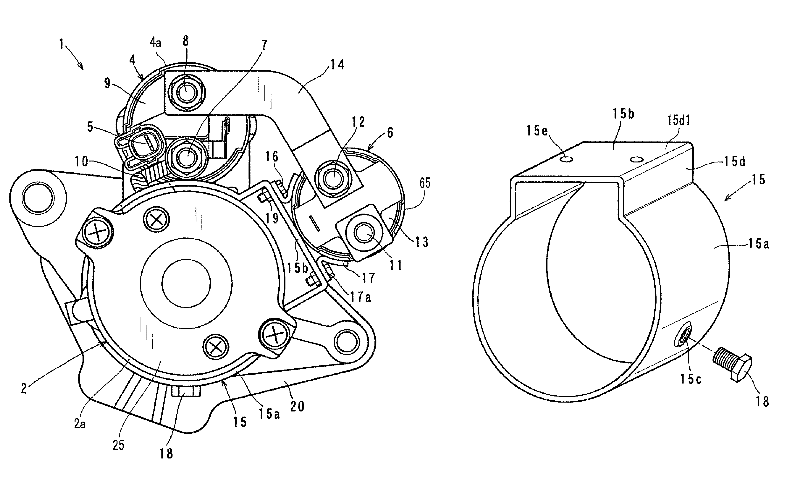
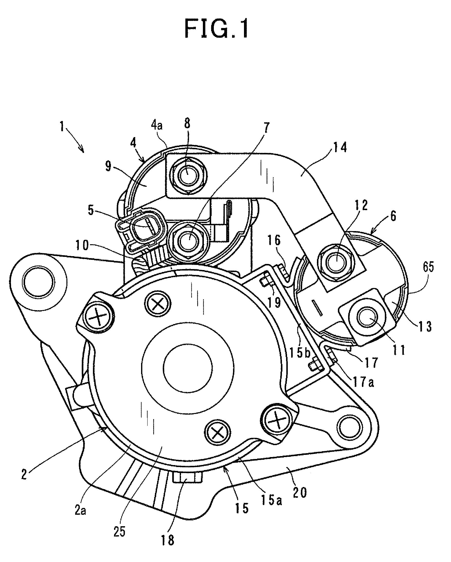
[0036]FIGS. 1 and 2 together show the overall configuration of a starter 1 according to the first embodiment of the invention. The starter 1 is designed to start an internal combustion engine of a motor vehicle.
[0037]As shown in FIGS. 1 and 2, the starter 1 includes: a motor 2 that generates torque upon being supplied with electric power; a pinion 3 that is configured to mesh with a ring gear 3a of the engine to transmit the torque generated by the motor 2 to the engine; a shift lever 33 that is configured to shift the pinion 3 in the axial direction of the starter 1 to bring the pinion 3 into and out of mesh with the ring gear 3a; a main electromagnetic switch 4 that selectively opens and closes an electric circuit for supplying electric power from a battery 30 to the motor 2 (to be simply referred to as motor circuit hereinafter); an auxiliary electromagnetic switch 6 that switches the motor circuit between a high-resistance path and a low-resistance path; and a ...
second embodiment
[Second Embodiment]
[0096]FIG. 6 shows the configuration of a fixing band 15 according to the second embodiment of the invention.
[0097]As shown in FIG. 6, in the present embodiment, the fixing band 15 is also configured to include a band portion 15a and a seat portion 15b.
[0098]The seat portion 15b is identical to the seat portion 15b according to the first embodiment. However, the band portion 15a is different from the band portion 15a according to the first embodiment.
[0099]More specifically, in the present embodiment, the band portion 15b is divided in its circumferential direction to have an opposite pair of end parts 15f. The end parts 15f are bent to extend radially outward and face each other in the circumferential direction with a gap formed therebetween. In addition, each of the end parts 15f has a through-hole 15f1 formed therein.
[0100]In fixing the fixing band 15 to the motor yoke 2a, the fixing band 15 is first placed so that the band portion 15a of the fixing band 15 su...
third embodiment
[Third Embodiment]
[0106]FIG. 7 shows the configuration of a fixing band 15 according to the third embodiment of the invention.
[0107]As shown in FIG. 7, in the present embodiment, the fixing band 15 is also configured to include a band portion 15a and a seat portion 15b.
[0108]The band portion 15a is identical to the band portion 15a according to the first embodiment; thus it can be fixed to either the motor yoke 2a or the yoke 4a of the main electromagnetic switch 4 in the same manner as described in the first embodiment.
[0109]However, the seat portion 15b is different from the seat portion 15b according to the first embodiment. Specifically, referring further to FIG. 8C, in the present embodiment, the seat portion 15b has a pair of slits 15g that are formed through the end wall 15d1 to extend parallel to each other with a predetermined distance therebetween.
[0110]On the other hand, the auxiliary electromagnetic switch 6 includes, as shown in FIGS. 8A-8B, a pair of brackets 17 each ...
PUM
 Abstract
Description
Claims
Application Information
 - R&D
- Intellectual Property
- Life Sciences
- Materials
- Tech Scout
- Unparalleled Data Quality
- Higher Quality Content
- 60% Fewer Hallucinations
Browse by: Latest US Patents, China's latest patents, Technical Efficacy Thesaurus, Application Domain, Technology Topic, Popular Technical Reports.
© 2025 PatSnap. All rights reserved.Legal|Privacy policy|Modern Slavery Act Transparency Statement|Sitemap|About US| Contact US: help@patsnap.com


