Induced field determination using diffuse field reciprocity

a technology of diffuse field and electromagnetic field, applied in the direction of reradiation, instruments, material impedance, etc., can solve the problems of numerous potential sources of electromagnetic interference, potential harmful currents could be induced in vehicle wiring systems, and electromagnetic interference is a common phenomenon

Active Publication Date: 2015-08-25
DASSAULT SYSTEMES SIMULIA CORP +1
View PDF4 Cites 0 Cited by
  • Summary
  • Abstract
  • Description
  • Claims
  • Application Information

AI Technical Summary

Problems solved by technology

Electromagnetic interference is a common problem that designers of electrical circuits, devices, and systems are concerned with due to the potential of electromagnetic interference disrupting normal operation of such electrical circuits, devices, and systems.
In practice, there are numerous potential sources of electromagnetic interference.
Thus, there are many situations in which potentially harmful currents could be induced in vehicle wiring systems by electromagnetic fields.
For example, a typical mobile phone transmitter may produce excitation at around 2 GHz, leading to a wavelength of 15 cm, meaning that the electromagnetic field will have a spatially complex distribution within a typical automotive vehicle interior.
While there are numerous existing modeling methods, calculating the response to the electromagnetic interference using these approaches requires a significant amount of computation time and resources.

Method used


Image

  • Induced field determination using diffuse field reciprocity
  • Induced field determination using diffuse field reciprocity
  • Induced field determination using diffuse field reciprocity

Examples


Embodiment Construction

[0024]The following detailed description is merely illustrative in nature and is not intended to limit the embodiments of the subject matter or the application and uses of such embodiments. As used herein, the word “exemplary” means “serving as an example, instance, or illustration,” and any implementation described herein as exemplary is not necessarily to be construed as preferred or advantageous over other implementations. Furthermore, there is no intention to be bound by any expressed or implied theory presented in the preceding technical field, background, or the following detailed description.

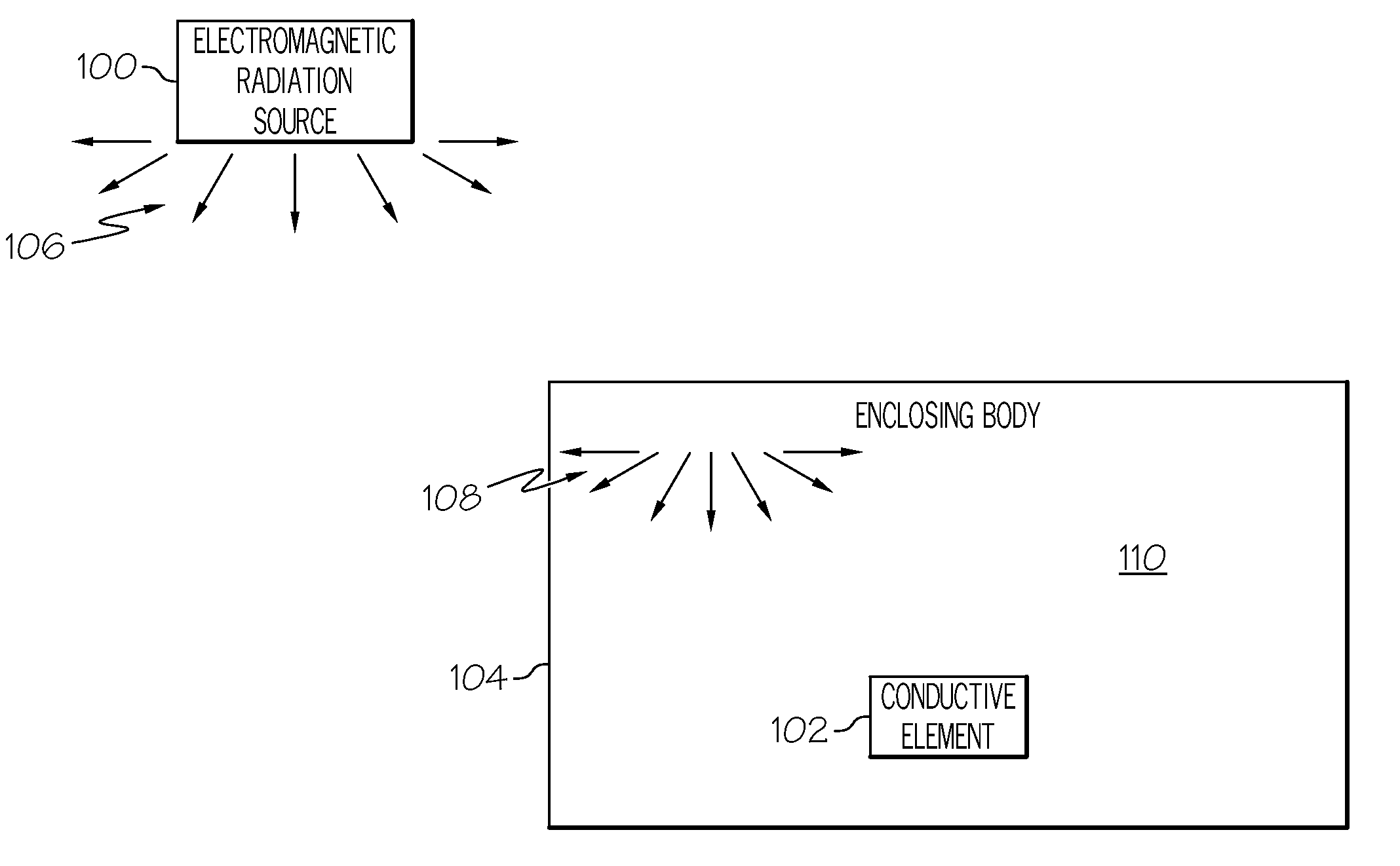
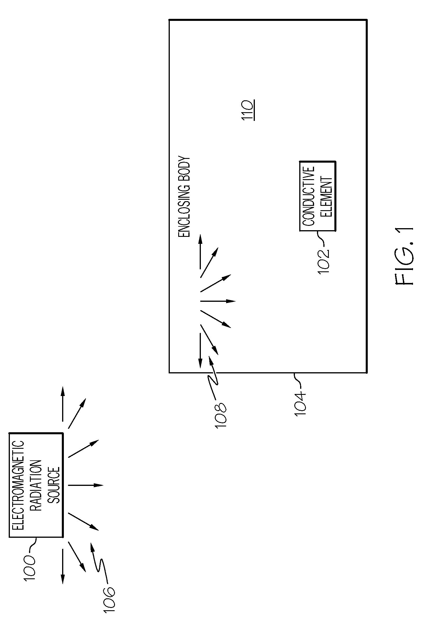
[0025]FIG. 1 depicts a simplified representation of an exemplary operative environment having an electromagnetic radiation source 100 capable of inducing electromagnetic fields in a conductive element 102 within an enclosing body 104. In practice, the electromagnetic radiation source 100 may be any source of electromagnetic radiation, such as for example, cellular base stations, wireless ...


PUM


Abstract

Methods and systems are provided for determining the surface electromagnetic impedance of a conductive element and applying the diffuse field reciprocity principle using that surface electromagnetic impedance to determine electric fields induced in the conductive element. An exemplary method involves determining a surface electromagnetic impedance matrix for the conductive element based on its physical dimensions and an excitation frequency for an incident electromagnetic wavefield, applying diffuse field reciprocity to determine a metric indicative of an induced field based on the surface electromagnetic impedance matrix and an energy metric for the incident electromagnetic wavefield, and displaying a graphical representation of the metric on a display device.

Description

CROSS-REFERENCE TO RELATED APPLICATION(S)[0001]This application claims the benefit of U.S. provisional patent application Ser. No. 61 / 474,367, filed Apr. 12, 2011, the entire content of which is incorporated by reference herein.TECHNICAL FIELD[0002]The subject matter described herein relates generally to determining induced electromagnetic fields, and more particularly, embodiments of the subject matter relate to calculating induced electromagnetic fields using diffuse field reciprocity principles.BACKGROUND[0003]Electromagnetic interference is a common problem that designers of electrical circuits, devices, and systems are concerned with due to the potential of electromagnetic interference disrupting normal operation of such electrical circuits, devices, and systems. In practice, there are numerous potential sources of electromagnetic interference. For example, a designer of an electrical system for an automotive vehicle must be concerned with various potential sources of electroma...

Claims


Application Information

Patent Timeline
Patent Type & Authority Patents(United States)
IPC IPC(8): G06F7/60G06F17/10G06F17/50G01V3/165
CPCG06F17/5018G01V3/165G01V2210/6163G06F30/23G01R29/0814G01N27/02G01R13/02G01R21/133G01R23/16G01R29/0892G06F17/18
Inventor LANGLEY, ROBIN STEWART
Owner DASSAULT SYSTEMES SIMULIA CORP
Why Eureka
Try Eureka