Frequency-feedback cavity enhanced spectrometer

a cavity-enhanced, frequency-feedback technology, applied in the field of cavity-enhanced absorption spectroscopy, can solve the problems of affecting the lifetime of the cavity, the recording rate must be significantly faster than the cavity lifetime, and the signal depends not only on losses

Active Publication Date: 2015-08-18
SOUTHWEST SCI
View PDF12 Cites 11 Cited by
  • Summary
  • Abstract
  • Description
  • Claims
  • Application Information

AI Technical Summary

Benefits of technology

The present invention is a spectrometer and methods for measuring cavity losses in a cavity. It uses a light source, detector, and feedback electronics to create oscillation of the optical signal on the detector. The cavity can be made with at least two mirrors enclosing a gaseous or liquid sample, or an optical fiber. One or more amplifiers and phase shifters can create self-oscillation at a target frequency. A phase locked loop is employed to generate a clock signal that is used to modulate the light source. The oscillation frequency is measured at a number of preset modulation phases to determine an estimate of cavity loss that is substantially independent of multiexponential behavior of the cavity. The technical effects of the invention include improved accuracy and reliability in measuring cavity losses, particularly in difficult samples.

Problems solved by technology

This approach has the advantage of simple implementation, but the disadvantage that the signal depends not just on losses in the cavity, but also on losses in the optical path outside the cavity and on variations in the efficiency of both the source and the detector.
A disadvantage of the ring-down approach is that the recording rate has to be significantly faster than the cavity lifetime.
This high recording rate becomes especially problematic when the cavity lifetime is short.
If the phase shift measurement is implemented by separate analog x and y demodulations, then gain errors between the x and y channels can introduce calibration errors.
If the phase measurement is implemented by digital means, then digitization effects may limit the resolution with which the phase can be measured.
Thus, detection with such a lock-in amplifier will not achieve the full theoretical precision.
Furthermore, digital phase detection methods are difficult to apply at high frequencies associated with cavities that have short storage times.
When a wavelength-dependent absorption feature is present, it interacts more strongly with one of the sidebands, and this unbalances the transmitted power so that the light transmitted by the cavity is modulated.

Method used


Image

  • Frequency-feedback cavity enhanced spectrometer
  • Frequency-feedback cavity enhanced spectrometer
  • Frequency-feedback cavity enhanced spectrometer

Examples


Embodiment Construction

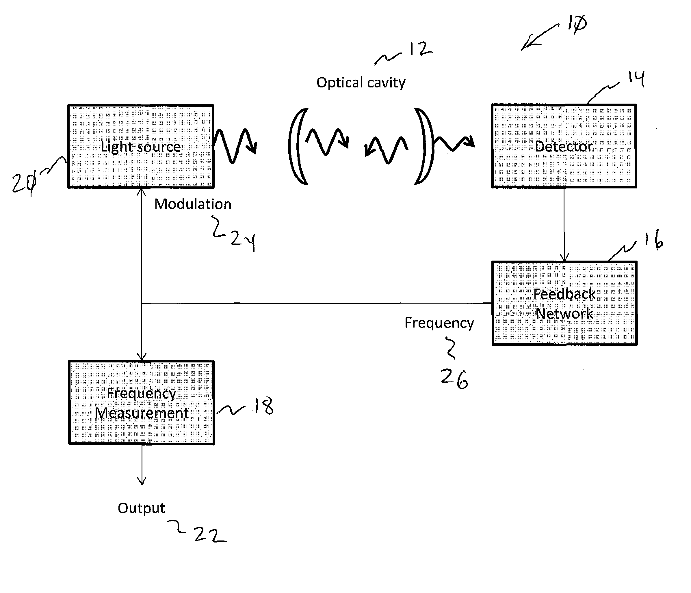
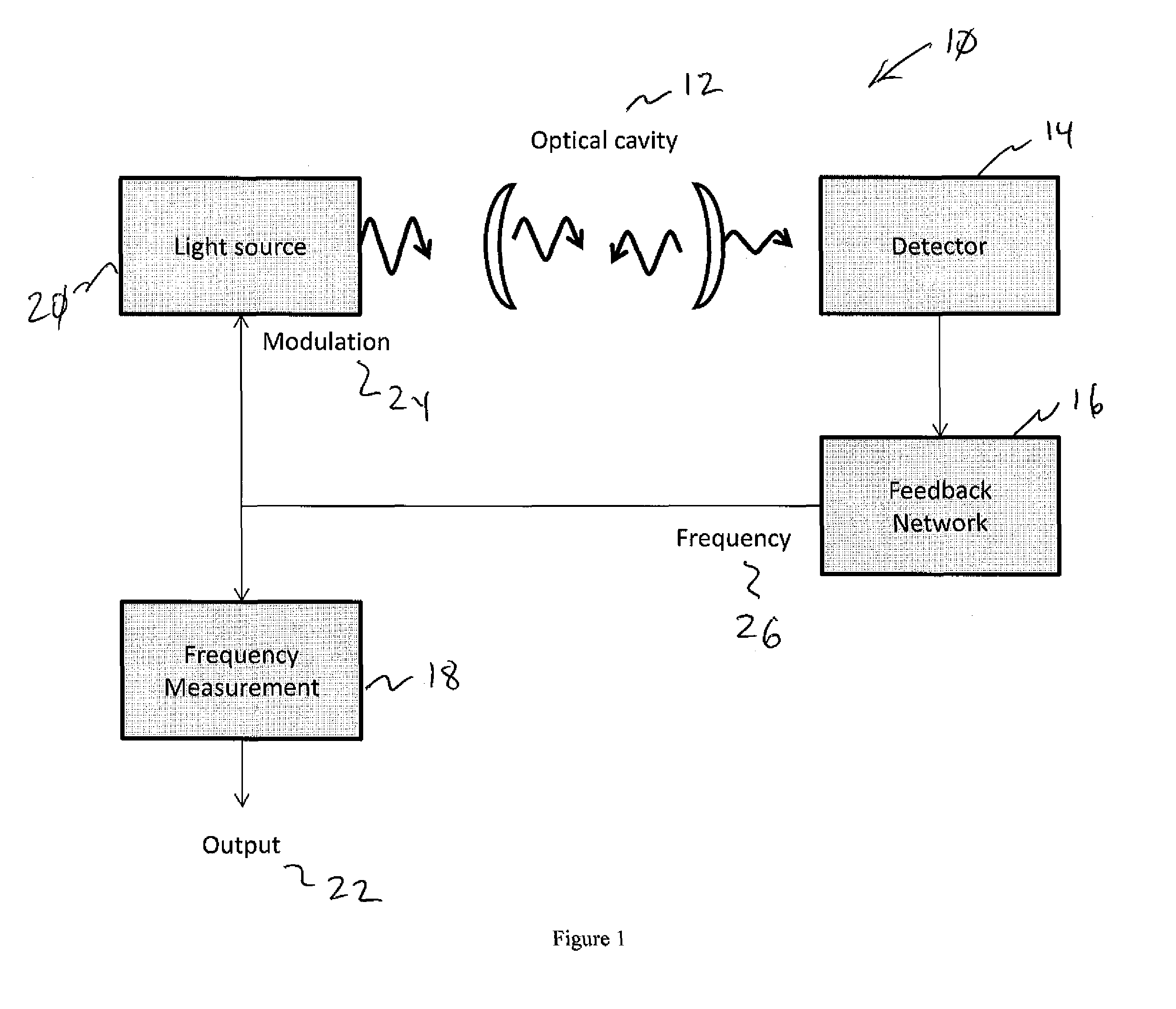
[0028]The present invention can measure the losses in an optical cavity without requiring a careful measurement of the amplitude of the detection signal. The invention does not require careful adjustment of the relative gains of two amplifiers. The invention does not require a microphone or an acoustic resonance frequency. The invention does not require a linear, calibrated phase detector. The invention operates at the most sensitive frequency regardless of changes in the optical losses within the cavity.

[0029]For purposes of the specification and claims, the following definitions are employed: Light means electromagnetic radiation regardless of wavelength or energy. Modulation means a method for changing the amplitude, phase, or frequency of light. Detector means a device that can produce an electrical signal proportional to the power or intensity or electric field of the light that is incident on the detector. Optical path means the distance a photon travels through the sample bef...


PUM


Abstract

A spectrometer comprising an optical cavity, a light source capable of producing light at one or more wavelengths transmitted by the cavity and with the light directed at the cavity, a detector and optics positioned to collect light transmitted by the cavity, feedback electronics causing oscillation of amplitude of the optical signal on the detector at a frequency that depends on cavity losses, and a sensor measuring the oscillation frequency to determine the cavity losses.

Description

STATEMENT REGARDING FEDERALLY SPONSORED RESEARCH OR DEVELOPMENT[0001]This invention was made with government support under Contract No. DE-SC0007534 awarded by the U.S. Department of Energy. The government has certain rights in the invention.CROSS-REFERENCE TO RELATED APPLICATIONS[0002]Not Applicable.INCORPORATION BY REFERENCE OF MATERIAL SUBMITTED ON A COMPACT DISC[0003]Not Applicable.COPYRIGHTED MATERIAL[0004]Not Applicable.BACKGROUND OF THE INVENTION[0005]1. Field of the Invention (Technical Field)[0006]The present invention relates to absorption spectroscopy, particularly to cavity-enhanced absorption spectroscopy.[0007]2. Description of Related Art[0008]Note that the following discussion refers to a number of publications by author(s) and year of publication, and that due to recent publication dates certain publications are not to be considered as prior art vis-a-vis the present invention. Discussion of such publications herein is given for more complete background and is not t...

Claims


Application Information

Patent Timeline
IPC IPC(8): G01J3/10G01N21/25
CPCG01N21/255G01J3/021G01J3/10G01J3/42G01J3/433G01N21/39G01N21/552G01N2201/065
Inventor HOVDE, DAVID CHRISTIANGOMEZ, ANTHONY
Owner SOUTHWEST SCI
Why Eureka
Try Eureka