Battery system component layout structure for electrically driven vehicle

a technology of battery system and layout structure, applied in the direction of electric devices, vehicle sub-unit features, jet propulsion mounting, etc., can solve the problem that the propulsion battery cannot be protected from the rear

Active Publication Date: 2015-07-28
NISSAN MOTOR CO LTD
View PDF6 Cites 17 Cited by
  • Summary
  • Abstract
  • Description
  • Claims
  • Application Information

AI Technical Summary

Benefits of technology

[0009]Accordingly, at the time of rear collision, the auxiliary battery, which is disposed in a vehicle rear side space rearward of the propulsion battery and in an position in which the auxiliary battery overlaps with the propulsion battery with respect to the vehicle longitudinal direction, receives the impact force due to a rear end collision first and thus serves as a buffer member for absorbing an impact energy and protects the propulsion battery. Thus, by using the auxiliary battery, which is arranged together with the propulsion or driving battery in the rear room, as a buffer member, it is possible to protect the propulsion battery from the rear collision impact.

Problems solved by technology

Therefore, at the time of rear collision when the vehicle is hit from the rear of the vehicle, there is a problem that an impact force would be simultaneously input to the propulsion battery and the auxiliary battery so that the propulsion battery cannot be protected from the rear collision impact.

Method used


Image

  • Battery system component layout structure for electrically driven vehicle
  • Battery system component layout structure for electrically driven vehicle
  • Battery system component layout structure for electrically driven vehicle

Examples


first embodiment

[0016]First, a configuration is described. The configuration of the battery cooling structure for the FF plug-in hybrid vehicle (as an example of the electrically driven vehicles) will be described in an “overall system configuration”, a “layout structure of the battery system components”, and a “cooling structure of the battery system components”, separately.

[0017]Overall System Configuration

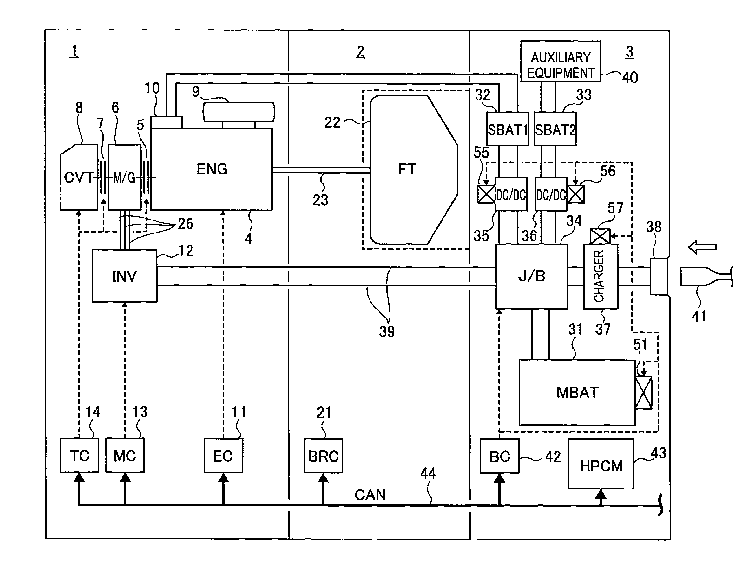
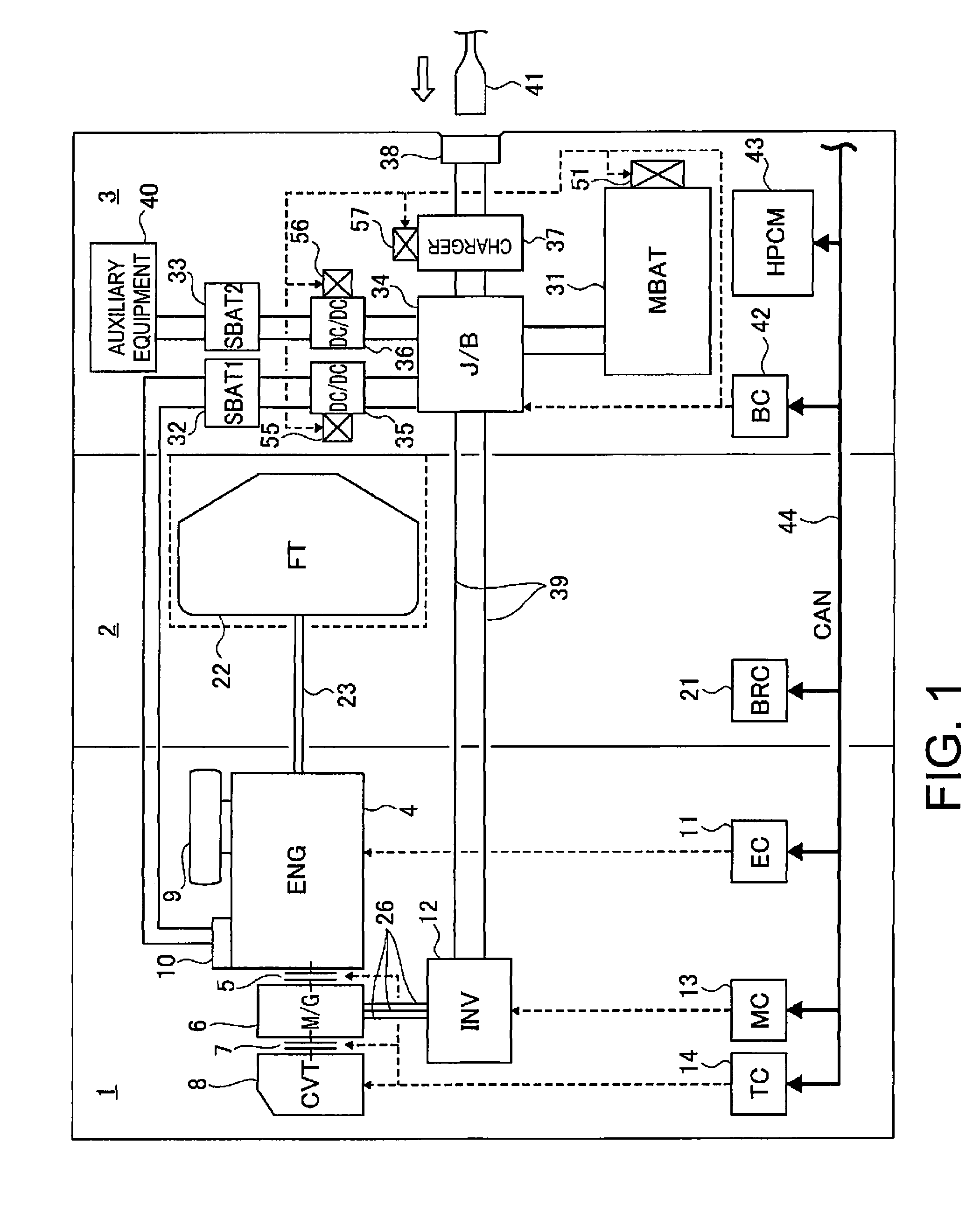
[0018]FIG. 1 is an overall system diagram illustrating an FF plug-in hybrid vehicle to which a battery cooling structure of the first embodiment is applied. Below, with reference to FIG. 1, description is given of the overall system configuration of the plug-in hybrid vehicle.

[0019]As shown in FIG. 1, the FF plug-in hybrid vehicle is divided into three spaces, i.e., a front room or compartment 1 on the vehicle front side for mounting power train system components, a center room or compartment 2 where a driver and an occupant are seated, and a rear room or compartment 3 at the vehicle rear side ...


PUM

PropertyMeasurementUnit
poweraaaaaaaaaa
widthaaaaaaaaaa
impact forceaaaaaaaaaa

Abstract

A vehicle battery system component layout structure is basically provided with a center room, a rear room, a vehicle propulsion battery and an auxiliary battery. The center room of a vehicle is configured to seat a driver and a passenger. The rear room of the vehicle is disposed rearward of the center room. The vehicle propulsion battery is disposed in a vehicle front side space in the rear room. The auxiliary battery is disposed in a vehicle rear side space in the rear room rearward of the propulsion battery and in a position in which the auxiliary battery overlaps with the propulsion battery in a vehicle longitudinal direction as viewed from a rear end of the vehicle.

Description

CROSS-REFERENCE TO RELATED APPLICATIONS[0001]This application is a U.S. National stage of International Application No. PCT / JP2013 / 050597, filed Jan. 16, 2013. This application claims priority to Japanese Patent Application No. 2012-006668, filed on Jan. 17, 2012. The entire disclosure of Japanese Patent Application No. 2012-006668 is hereby incorporated herein by reference.BACKGROUNDTechnical Field[0002]1. Field of the Invention[0003]The present invention relates to a battery system element or component layout structure for an electrically driven vehicle in which a battery for vehicle propulsion (propulsion battery) and a battery for auxiliary equipment or components (auxiliary battery) are arranged in a rear room of the rear part of the vehicle.[0004]2. Background Information[0005]Conventionally, in a battery system component layout structure of the electrically driven vehicle, it is known that the propulsion battery is disposed in a rear room of the rear part of the vehicle and t...

Claims


Application Information

Patent Timeline
Patent Type & Authority Patents(United States)
IPC IPC(8): B60R16/04B60K1/04B60L11/18H01M10/60B60L11/14B60L3/00B60R16/02B60K5/04B60K11/06B60K1/00B60L50/16
CPCB60R16/04B60K1/04B60K5/04B60K11/06B60K2001/003B60K2001/005B60K2001/0416B60L3/00B60L11/14B60L11/18B60R16/02H01M10/50B60Y2306/01B60L50/50B60L58/20B60L58/26B60L50/16Y02E60/10Y02T10/70H01M10/60
Inventor KARASHIMA, RYUSUKE
Owner NISSAN MOTOR CO LTD
Why Eureka
Try Eureka