
Methods and devices for optimizing the operation of a semiconductor optical modulator

a technology of optical modulator and operation optimization, which is applied in the direction of electromagnetic transmission, electrical equipment, transmission, etc., can solve the problems of modulator operation failing, modulator operation failing, and peak voltage of applied signal exceeding the forward bias threshold of the pn junction

Active Publication Date: 2015-07-14
NAT TECH & ENG SOLUTIONS OF SANDIA LLC
View PDF4 Cites 6 Cited by
  • Summary
  • Abstract
  • Description
  • Claims
  • Application Information

AI Technical Summary

Benefits of technology

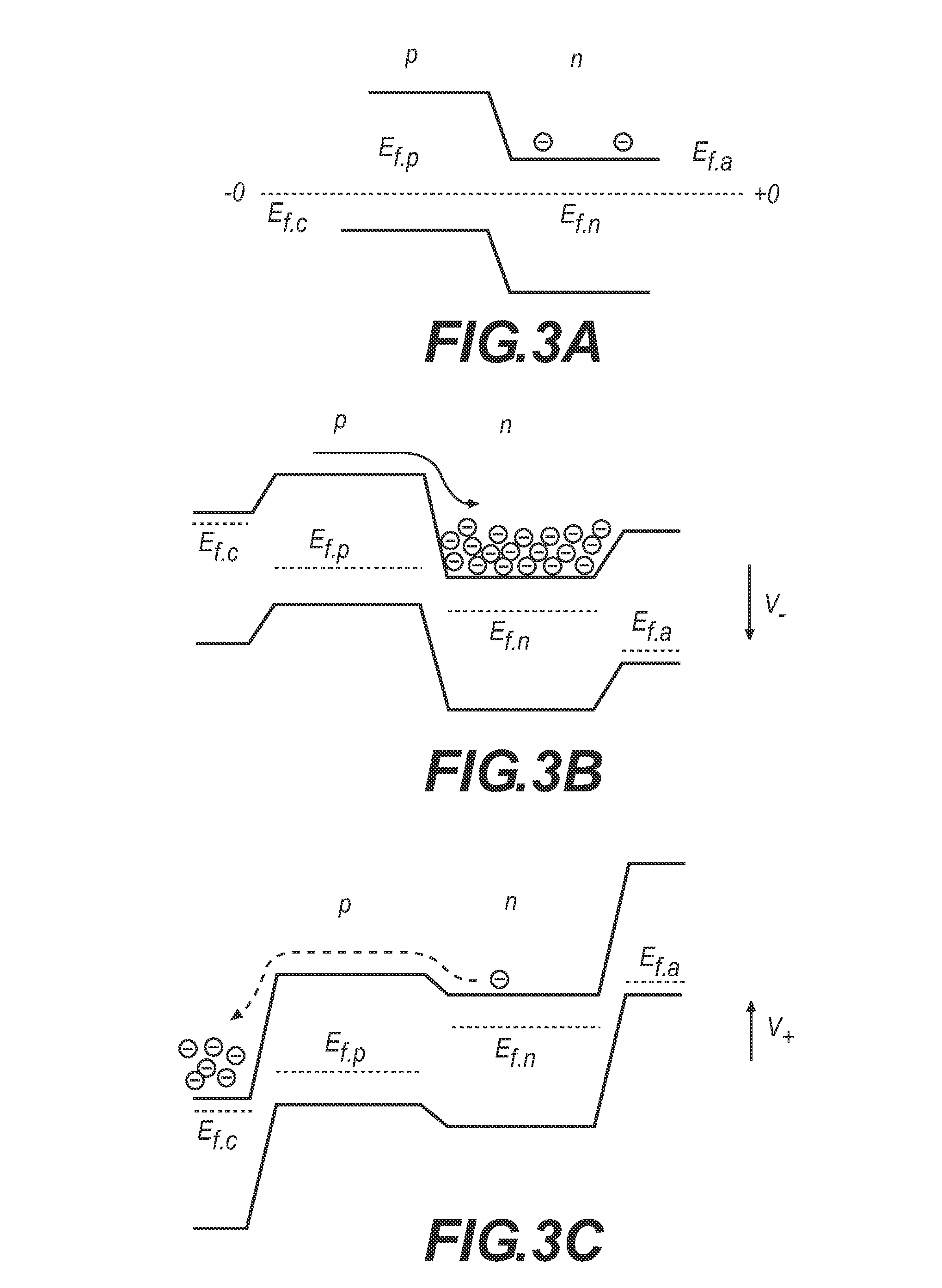
The patent text explains that using a modulator with a limited forward bias point of 0 Volts can result in lower extinction ratio of the transmitter. To maximize the extinction ratio while minimizing the drive voltage, it is desirable to drive the modulator to the edge of its diode turn-on voltage. This leads to a maximum width depletion region that is advantageous for small temperature variations. The technical effect of this invention is to improve the performance of the transmitter by maximizing the extinction ratio while minimizing the required drive voltage.

Problems solved by technology

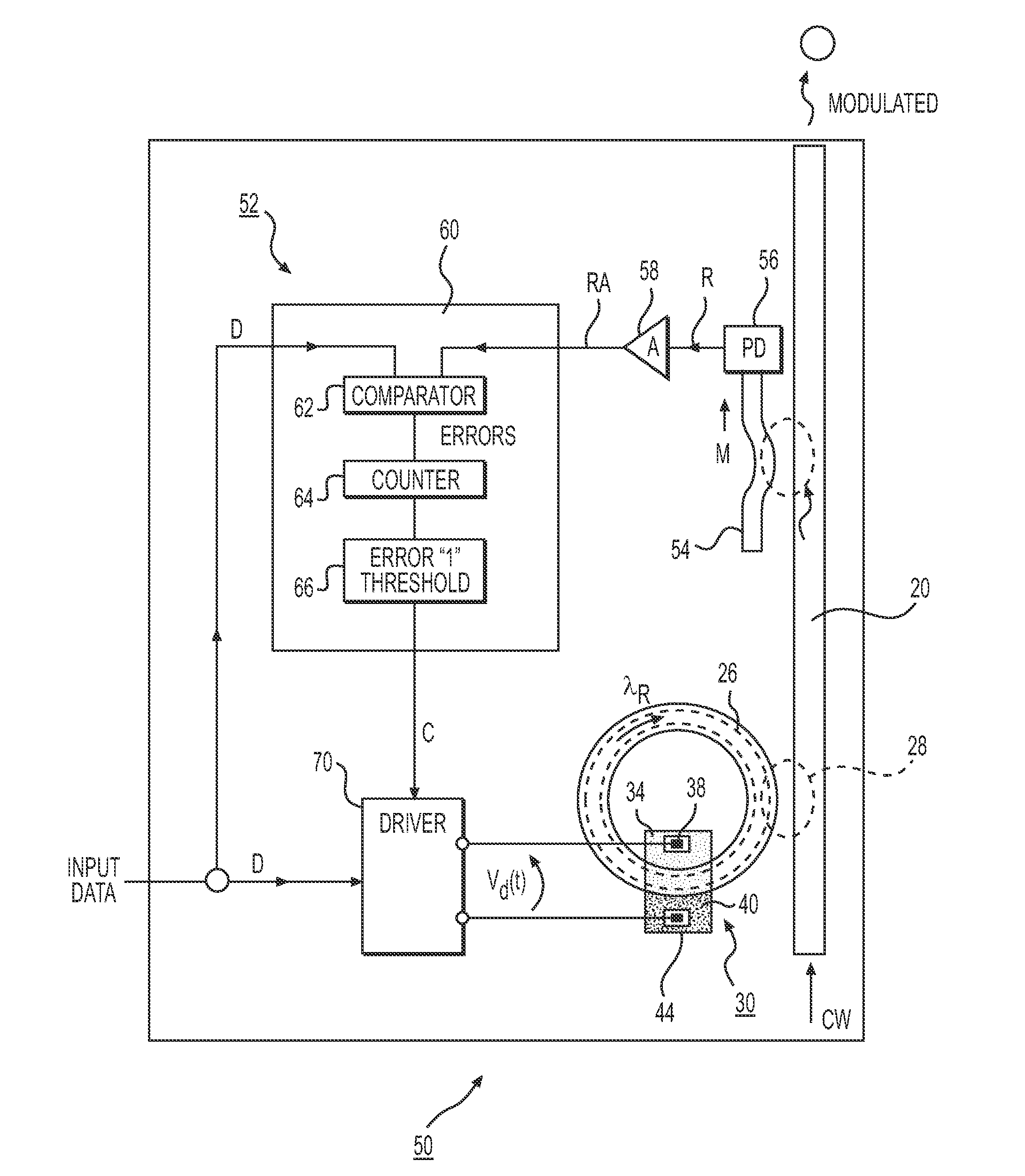
However, the aforementioned modulator operation may fail if the DC bias placed on an electrical signal input into the modulator increases to a value where diode turn-on occurs, thus injecting carriers into the diode region.
Modulator operation may also fail if the amplitude of the electrical signal (at a given bias point) causes the modulator to operate in a forward-bias condition.
However, modulators that are monolithically integrated with CMOS devices, or are used in high-temperature applications, harsh environments, or at data rates in excess of 10 GHz can reach forward bias at lower drive voltage thresholds.
Additionally, normal aging of a device may result in changes to its peak voltage over time, and result in the peak voltage of the applied signal exceeding the forward bias threshold of the pn junction.
Furthermore, limiting the forward bias point of a modulator to 0 Volts (V) may limit the extinction ratio of the transmitter.

Method used


Image

  • Methods and devices for optimizing the operation of a semiconductor optical modulator
  • Methods and devices for optimizing the operation of a semiconductor optical modulator
  • Methods and devices for optimizing the operation of a semiconductor optical modulator

Examples


Embodiment Construction

[0020]Throughout the following description and drawings, like reference numbers and / or characters refer to like elements. It should be understood that, although specific exemplary embodiments are discussed herein there is no intent to limit the scope of present invention to such embodiments. To the contrary, it should be understood that the exemplary embodiments discussed herein are for illustrative purposes, and that modified and alternative embodiments may be implemented without departing from the scope of the present invention.

[0021]It should be further noted that some exemplary embodiments may be described and claimed as a process or method (hereafter “method”). Though a method may be described and claimed as set of sequential steps, it should be understood that the steps may be performed in parallel, concurrently or simultaneously. In addition, the order of each step within a method may be re-arranged. A method may be terminated when completed, and may also include additional s...


PUM


Abstract

A semiconductor-based optical modulator includes a control loop to control and optimize the modulator's operation for relatively high data rates (above 1 GHz) and / or relatively high voltage levels. Both the amplitude of the modulator's driving voltage and the bias of the driving voltage may be adjusted using the control loop. Such adjustments help to optimize the operation of the modulator by reducing the number of errors present in a modulated data stream.

Description

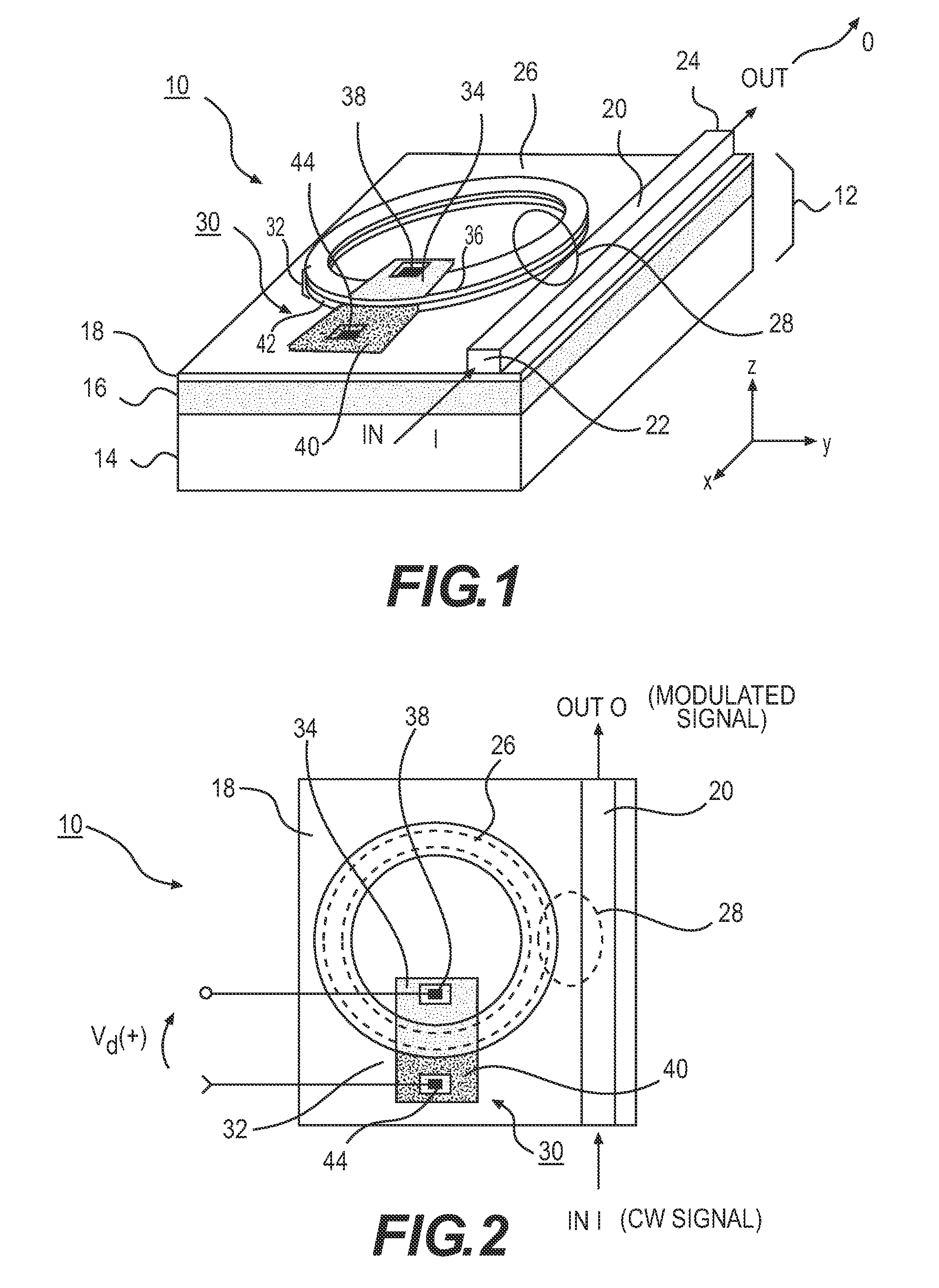
GOVERNMENT LICENSE RIGHTS[0001]This invention was developed under Contract DE-AC04-94AL85000 between Sandia Corporation and the U.S. Department of Energy. The U.S. Government has certain rights in this invention.INTRODUCTION[0002]Devices for altering the propagation of electromagnetic radiation, such as by modulation, represent fundamental building blocks for many technical endeavors. Modulation refers generally to the time-wise variation of a property of an electromagnetic wave or signal, these properties including, without limitation, amplitude, phase, spectral content, polarization, or the like. A time-varying control signal (oftentimes, a data signal) is used as a source to impart the modulation. Optical modulation refers to the modulation of at least one optical signal, where “electro-optic” modulation in particular refers to the use of an electrical input signal (generally a data signal) to modulate a continuous wave (CW) optical signal.[0003]In some arrangements, an electro-o...

Claims


Application Information

Patent Timeline
Patent Type & Authority Patents(United States)
IPC IPC(8): H04B10/079
CPCH04B10/07953H04B10/50575
Inventor ZORTMAN, WILLIAM A.
Owner NAT TECH & ENG SOLUTIONS OF SANDIA LLC
Learn More