
Controlling the extinction ratio in optical networks

a technology of optical fiber network and extinction ratio, applied in the field of optical fiber network, can solve the problems of increased transmitted power due to non-ideal, power penalty, etc., and achieve the effect of accurately controlling extinction ratio, enabling the control of extinction ratio in optical fiber network, and reducing power penalty

Inactive Publication Date: 2005-02-10
SOTO WALTER G +1
View PDF12 Cites 23 Cited by
  • Summary
  • Abstract
  • Description
  • Claims
  • Application Information

AI Technical Summary

Benefits of technology

Advantages of the invention can include one or more of following. Aspects of the invention enable the control of extinction ratio in optical fiber networks without the use of ancillary detectors such as photodiodes dedicated exclusively for extinction ratio monitoring. This allows extinction ratio to be controlled with fewer components than conventional systems. Moreover, aspects of the invention accurately control extinction ratio by using optical transceivers capable of accurately detecting high and low power levels in the data signal. Further, aspects of the invention provide for an efficient way to maintain an optical network over time as components reach their end of life.

Problems solved by technology

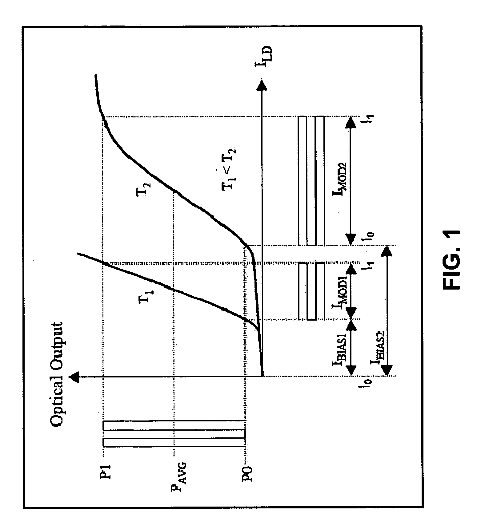
In most practical optical transmitters, however, the laser must be biased so that P0 is in the vicinity of the laser threshold, meaning that a finite amount of optical power is emitted at the low level and thus P0>0. This increase in transmitted power due to non-ideal values of extinction ratio is called the “power penalty”.

Method used


Image

  • Controlling the extinction ratio in optical networks
  • Controlling the extinction ratio in optical networks
  • Controlling the extinction ratio in optical networks

Examples


Embodiment Construction

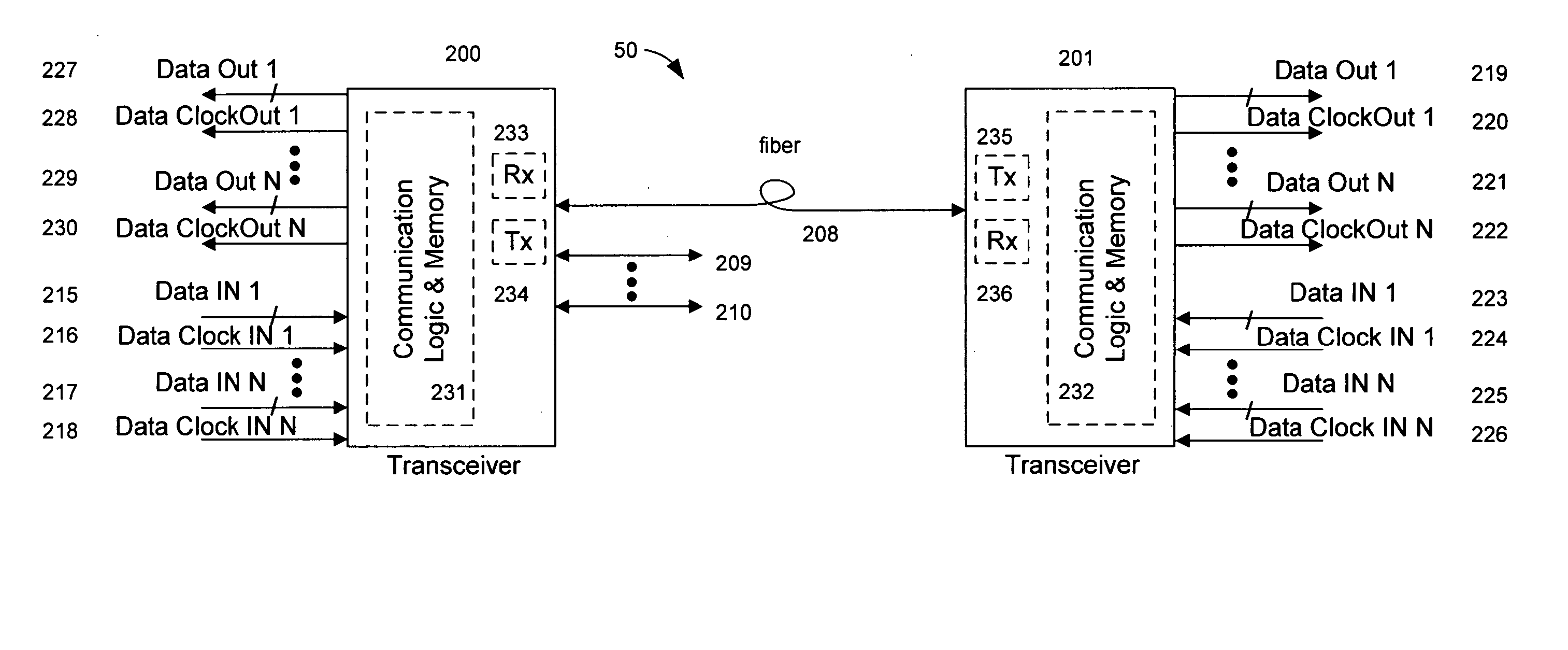
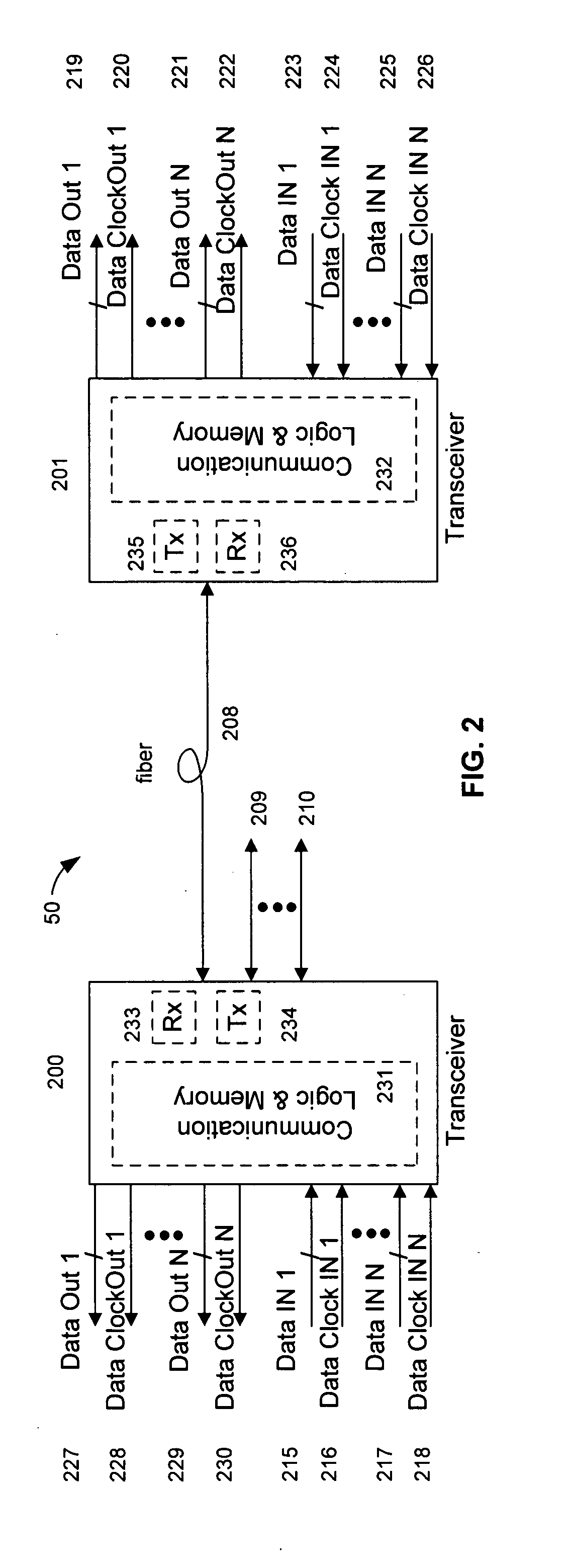
FIG. 2 shows a high-level fiber optic data network 50. The network includes a first transceiver 200 in communication with a second transceiver 201 via a fiber 208. The first transceiver 200 and the second transceiver 201 include transmitter circuitry (Tx) 234, 235 to convert electrical data input signals into modulated light signals for transmission over the fiber 208. In addition, the first transceiver 200 and the second transceiver 201 also include receiver circuitry (Rx) 233, 236 to convert optical signals received via the fiber 208 into electrical signals and to detect and recover encoded data and / or clock signals. First transceiver 200 and second transceiver 201 may contain a micro controller (not shown) and / or other communication logic and memory 231, 232 for network protocol operation. Although the illustrated and described implementations of the transceivers 200, 201 include communication logic and memory in a same package or device as the transmitter circuitry 234, 235 and ...


PUM


Abstract

A method and system for controlling extinction ratio in an optical network is disclosed. A first optical transceiver sends modulated light to a second optical transceiver and a digital measurement of a signal parameter reflecting the optical power levels of the received modulated light is taken. The modulated light sent by the first optical transceiver is adjusted in accordance with the digital measurement.

Description

TECHNICAL FIELD This invention relates to optical fiber networks. BACKGROUND FIG. 1 shows optical power as a function of current for an optical transmitter over time. In general, digital optical communication systems transmit binary data using two levels of optical power, where the higher power level represents a binary 1 and the lower power level represents a binary 0. These two power levels can be represented as P1 and P0, where P1>P0 and the units of power are watts. The difference between P1 and P0 is an average power Pavg. In optical transmitters, electrical current is converted to optical power and in optical receivers optical power is converted back to electrical current. The electrical currents I1 and I0 are proportional to the corresponding optical power levels and are controlled by the limit on modulation (Imod) and bias (Ibias) currents of the transmitter's laser diode. The ratio between the high level and the low level shown in the equation below is defined as the ...

Claims


Application Information

Patent Timeline
Patent Type & Authority Applications(United States)
IPC IPC(8): H04BH04B10/00H04B10/04
CPCH04B10/40H04B10/0799
Inventor SOTO, WALTER G.SOTO, ALEXANDER I.
Owner SOTO WALTER G
Learn More