
Adaptive dead time control scheme for switch mode power converter with synchronous rectifiers topology

a dead time control and switch mode technology, applied in the field of switch mode power converters, can solve the problems of power loss and efficiency loss at light loads, shortening of sr by sr, etc., and achieve the effect of high efficiency

Active Publication Date: 2015-07-14
ANALOG DEVICES INC
View PDF3 Cites 11 Cited by
  • Summary
  • Abstract
  • Description
  • Claims
  • Application Information

AI Technical Summary

Benefits of technology

The patent describes a control scheme for a power converter that uses a specific topology. This control scheme can efficiently handle changes in the load being driven, resulting in higher overall efficiency.

Problems solved by technology

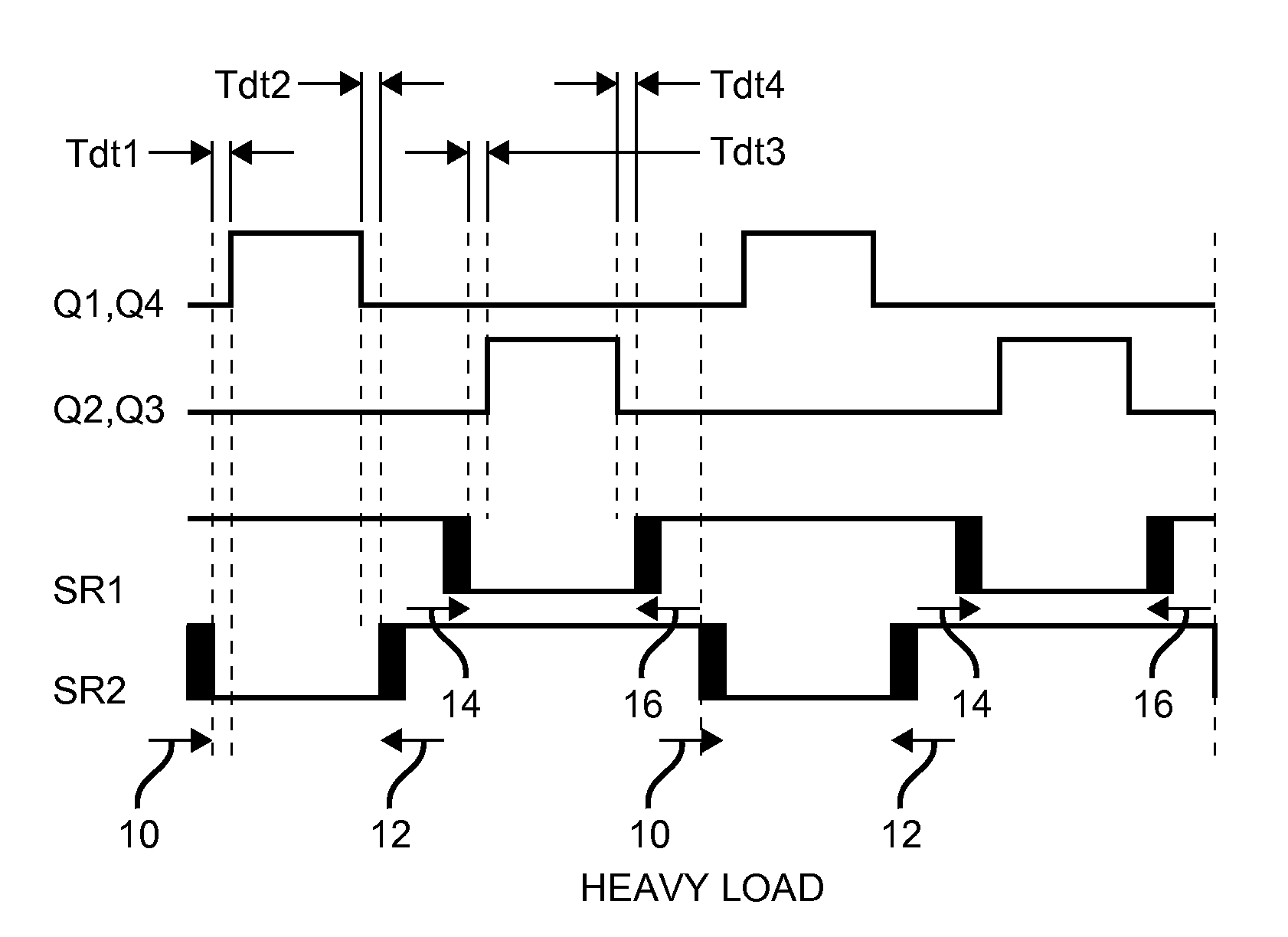
However, a light load the rate of change for primary side voltage VAB, such that a short dead time can result in VAB being shorted by SR1 and SR2 or prematurely forced to ±Vin before it reaches zero or Vin normally.
This would induce a large current in the circuitry, which causes power loss and loss of efficiency at light loads.
This may be unacceptable when there is a requirement that a supply meet a certain efficiency specification all across its load range, rather than just at a single load point.

Method used


Image

  • Adaptive dead time control scheme for switch mode power converter with synchronous rectifiers topology
  • Adaptive dead time control scheme for switch mode power converter with synchronous rectifiers topology
  • Adaptive dead time control scheme for switch mode power converter with synchronous rectifiers topology

Examples


Embodiment Construction

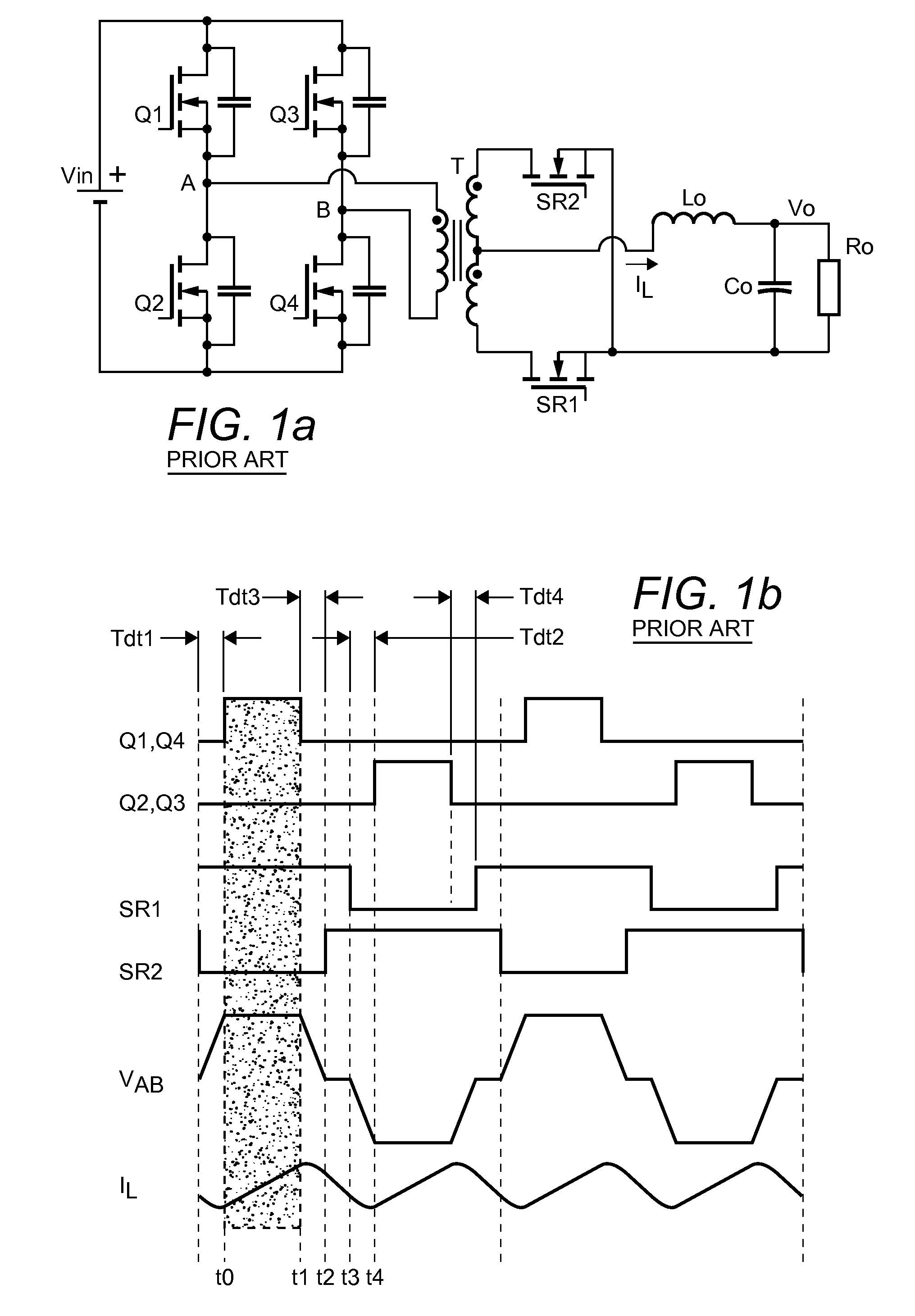
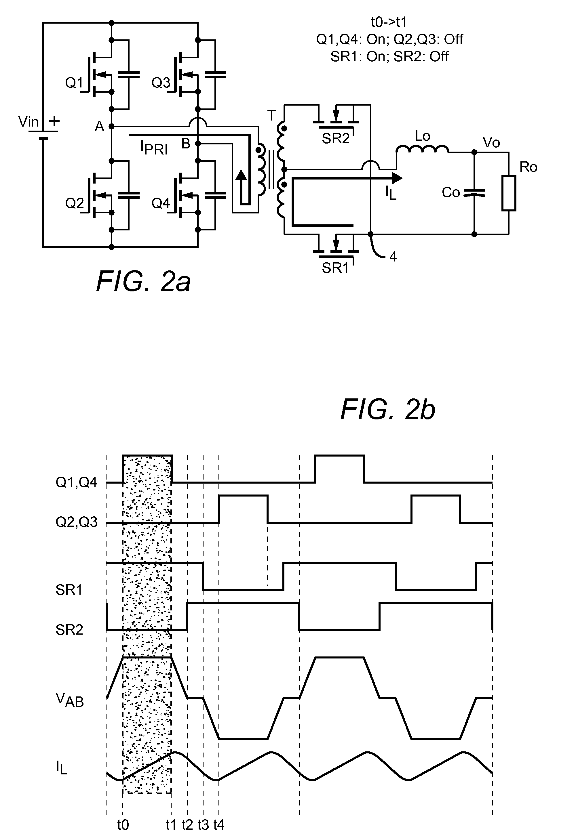
[0020]The operation of a power converter with a full bridge with SR topology is illustrated FIGS. 2a, 3a, 4a and 5a, along with corresponding timing diagrams 2b, 3b, 4b and 5b, respectively; in this example, the converter is arranged to operate in continuous conduction mode (CCM). Note that FIGS. 2a-5a only indicate one of the four “dead time” intervals as defined above. The basic converter topology is as described above: four transistors Q1-Q4 are arranged in a full bridge configuration, with the bridge's input connected across a DC input voltage Vin and the bridge's output—taken at circuit nodes A and B—connected across the primary winding of transformer T. Synchronous rectifiers SR1 and SR2 are connected respective sides of the transformer's secondary winding and a first node (labeled as node 4 in FIG. 2a), and inductor Lo is connected between a tap on the transformer's secondary winding and an output node at which output voltage Vo is provided. Output capacitor Co and load Ro ar...


PUM


Abstract

An adaptive dead time (ADT) control scheme for use with a switch mode power converter having a full bridge with synchronous rectifiers topology. A controller which implements the control scheme includes an input circuit arranged to receive a signal representative of the converter's output voltage, and an output circuit arranged to operate the converter's switching elements and synchronous rectifiers to produce a desired output voltage. The controller is further arranged such that the converter's “dead time” is adaptively varied in an inverse relationship to the magnitude of the load current. In a preferred embodiment, the signals used to operate the synchronous rectifiers are PWM signals, and the controller adaptively varies the dead time in a linear inverse relationship to the magnitude of the load current by modulating the rising and falling edges of the signals used to operate the synchronous rectifiers.

Description

BACKGROUND OF THE INVENTION[0001]1. Field of the Invention[0002]This invention relates generally to switch mode power converters, and more particularly to control schemes for operating a switch mode power converter with a full bridge with synchronous rectifiers topology.[0003]2. Description of the Related Art[0004]A power converter with a full bridge with synchronous rectifiers (SR) topology is shown in FIG. 1a. Such converters are often used in high power applications such as telecom, networking, servers, etc., in which the converter receives a DC input voltage typically in the range of 36-72 volts. In the exemplary embodiment shown, four transistors Q1-Q4 are arranged in a full bridge configuration, with the bridge's input connected across a DC input voltage Vin and its output—taken at circuit nodes A and B—connected across the primary winding of a transformer T. First and second synchronous rectifiers SR1 and SR2 are coupled between the secondary side of transformer T and an outp...

Claims


Application Information

Patent Timeline
Patent Type & Authority Patents(United States)
IPC IPC(8): H02M3/335H02M1/38
CPCH02M3/33592H02M1/38Y02B70/1475Y02B70/10
Inventor DUAN, JUNSHENG, HUAILIANGXIE, RENJIANYUAN, BOZHAI, JERRY
Owner ANALOG DEVICES INC
Learn More