Apparatus and method for examining a specimen by means of probe microscopy

a technology of specimens and microscopes, applied in the field of apparatus and methods for examining specimens by means of probe microscopy, can solve the problems of inability to use fibreglass probes or use only unsatisfactory for liquid measurements, and the lack of stability of upright microscopes in the nm range does not allow high-resolution measurements

Active Publication Date: 2015-06-23
BRUKER NANO INC +1
View PDF10 Cites 2 Cited by
  • Summary
  • Abstract
  • Description
  • Claims
  • Application Information

AI Technical Summary

Benefits of technology

[0017]The object of the invention is to specify an apparatus and a method for examining a specimen by means of probe microscopy, in particular scanning probe microscopy, by means of which the possibility of simultaneously examining the specimen by means of different microscopic techniques using a combined system of measurement devices is improved.
[0022]One preferred further development of the invention provides that the optical system is designed to extend the condenser light path. In this embodiment, the condenser light path, as would be obtained without use of the optical system, i.e. depending on the configuration of the condenser illumination, is extended. In this way, the distance between the outlet of the condenser illumination and the region of the specimen holder can be increased, which avoids any restrictions in particular with regard to an installation height of the measurement apparatus. As an alternative, the originally obtained condenser light path may also be shortened.
[0031]Preferably, one further development of the invention provides an optical observation channel which is configured for optical microscopy of the specimen. The design of the optical observation channel makes it possible to observe the specimen through said channel by means of optical microscopy on the specimen holder in the same position as is the case for the examination by means of probe microscopy.

Problems solved by technology

However, when using the light pointer principle, the problem occurs that the laser spot focussed onto the cantilever should be smaller than the width of the cantilever, in order to allow optimal detection of the bending of the cantilever.
However, due to the special distance detection (“shear force mode”) used therein, the fibreglass probes cannot be used or can be used only unsatisfactorily for measurements in liquids.
However, this implementation has the considerable disadvantage that the lack of stability of the upright microscope in the nm range does not allow a high-resolution measurement using the “objective” for atomic force microscopy, due to a tendency of the microscope to vibrate.

Method used


Image

  • Apparatus and method for examining a specimen by means of probe microscopy
  • Apparatus and method for examining a specimen by means of probe microscopy
  • Apparatus and method for examining a specimen by means of probe microscopy

Examples


Embodiment Construction

OF EMBODIMENTS OF THE INVENTION

[0041]The invention will be explained in more detail below on the basis of examples of embodiments and with reference to the figures of a drawing, in which:

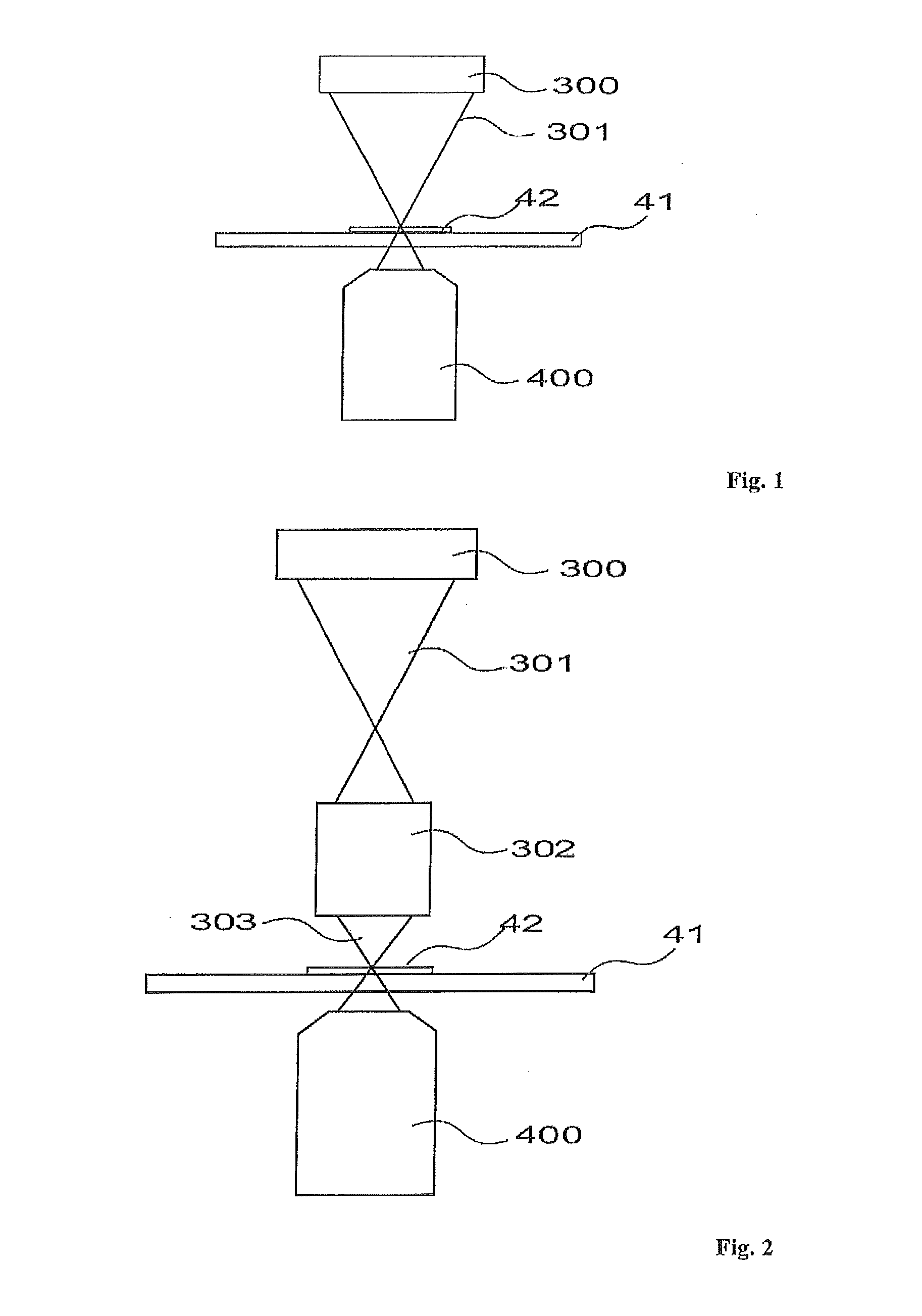
[0042]FIG. 1 shows a schematic view of an illumination of a specimen with condenser light for optical microscopy in a transmitted light configuration,

[0043]FIG. 2 shows a schematic view of an illumination of a specimen with condenser light for optical microscopy in a transmitted light configuration, wherein provided downstream of a condenser illumination is an optical system for projecting onto the specimen the condenser light emitted by the condenser illumination,

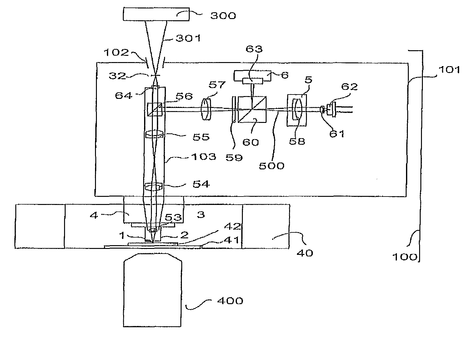
[0044]FIG. 3 shows a schematic view of an apparatus for examining a specimen by means of probe microscopy, in which there is additionally provided a light microscope in a transmitted light configuration,

[0045]FIG. 4 shows an enlarged view of the region of a specimen holder in the case of the apparatus in FIG. 3,

[0046]FIG. 5 shows a schemat...


PUM


Abstract

The invention relates to an apparatus and a method for examining a specimen by means of probe microscopy, in particular scanning probe microscopy. The apparatus comprises a probe microscope device which has a specimen holder for holding a specimen to be examined, a measurement probe and a displacement unit which is configured to displace the specimen holder and the measurement probe relative to one another for an examination of the specimen by means of probe microscopy, and comprises a condenser illumination and also an optical system which is arranged downstream of the condenser illumination and is configured to project condenser light, which is emitted by the condenser illumination in a condenser light path, into the region of the specimen holder for optical microscopy of the specimen to be examined, while at least partially maintaining condenser light parameters with which the condenser light is emitted by the condenser illumination.

Description

[0001]The invention relates to an apparatus and a method for examining a specimen by means of probe microscopy, in particular scanning probe microscopy.BACKGROUND OF THE INVENTION[0002]Using measurement or analysis technologies based on probe microscopy, a specimen to be examined is examined experimentally by detecting an influencing of a measurable property of a measurement probe by the specimen to be examined. During the examination of the specimen by means of scanning probe microscopy (SPM), a scanning of the specimen takes place by means of a relative movement between the measurement probe and the specimen. By way of example, a surface for analysis on the specimen is scanned.[0003]One method of scanning probe microscopy is atomic force microscopy (AFM). This serves for measuring surface properties of the specimen, for example the topography, with a high lateral and vertical resolution. The term “lateral resolution” here denotes the resolution in a plane of the surface to be exam...

Claims


Application Information

Patent Timeline
Patent Type & Authority Patents(United States)
IPC IPC(8): G01Q60/06G01Q30/02G02B21/00G02B21/08B82Y35/00
CPCG02B21/08B82Y35/00G02B21/002G01Q30/025
Inventor SOMMER, GUNNARKAMPS, JORN
Owner BRUKER NANO INC
Why Eureka
Try Eureka