
Golf club head with a compression-molded, thin-walled aft-body

a golf club head and compression molding technology, applied in the field of multi-material golf club heads, can solve the problems of increasing tool complexity, inability to create undercuts, and standard molding compounds that are not designed to be used in parts with very thin walls

Active Publication Date: 2015-05-19
TOPGOLF CALLAWAY BRANDS CORP
View PDF32 Cites 65 Cited by
  • Summary
  • Abstract
  • Description
  • Claims
  • Application Information

AI Technical Summary

Benefits of technology

The present invention relates to a driver type golf club head comprising a metal face cup and a composite aft body. The composite aft body is made from a molded compound of carbon fibers and a matrix material, and may include alignment markings. The composite aft body has a wall thickness of between 0.020 and 0.125 inches. The invention also includes a method of forming the composite aft body by pre-spreading carbon fiber bundles, mixing them with a matrix material, and compressing the mixture in a metal tooling mold to create a composite piece. The composite molding compound may include carbon nanotubes, carbon graphene platelets, or short carbon fibers. The invention also includes a golf club head comprising the composite aft body. The technical effects of the invention include improved performance and aesthetics of the driver type golf club head.

Problems solved by technology

There are various problems with the current process for manufacturing multiple material golf club heads.
For example, in a standard compression molding process, the hard metal tooling on both sides of the molding part makes it impossible to create undercuts without significantly increasing tool complexity.
Another problem lies in the fact that standard molding compounds are not designed to be used in parts with very thin walls.
When wall thicknesses are less than approximately 0.080 inches, it is difficult to compression mold most standard molding compounds.
Furthermore, standard molding compounds are not as strong, stiff, or tough as laminated composites made with similar matrix and fiber types.
Plies in a manufactured part can be made thicker by stacking two or more layers of the same fiber orientation on top of one another, but there is no reasonable way to create thinner plies without purchasing different, more expensive materials.
The limitation on the thickness of plies creates design constraints and limits the efficiency of even the best designs.
Even if analysis shows that 0.040 inches is thicker than necessary for the structural requirements of the part, the designer is limited by this minimum thickness.
This leads to inefficient parts that are overbuilt and heavier than they need to be.
Laminate composites also are not ideal because the raw materials typically used to make laminates are expensive.
This cost is compounded by the very high scrap rate involved in molding them.
Furthermore, the use of prepreg material requires hand placement of each layer of material into a mold, a time-consuming and labor-intensive process.
Another problem lies in the fact that latex bladders, which allow manufacturers to avoid undercut constraints, cause parts to lose definition on their inside surfaces.
As a result, it is difficult to predict the mass properties of a multiple-material body before a part is made.
One-piece bladder molded driver bodies also do not work well with a body-over-face joint.
The lack of precision on the inside of the head, however, makes it difficult to control the geometry of the body where it would meet up with the face.
Another problem lies with the fact that typical epoxy-based prepregs take at least twenty to thirty minutes, and often longer, to cure.
As such, bladders are a significant cost in the current multiple material golf club manufacturing process.

Method used


Image

  • Golf club head with a compression-molded, thin-walled aft-body
  • Golf club head with a compression-molded, thin-walled aft-body
  • Golf club head with a compression-molded, thin-walled aft-body

Examples


example 1

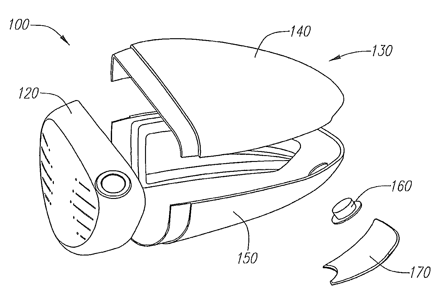
[0058]A preferred embodiment of a golf club head 10 formed using the molding compound and molding process of the present invention is shown in FIG. 10. The golf club head 100 is a driver-type head comprising a face cup 120 and an aft body 130 comprising a crown piece 140 and a sole piece 150. The golf club 100 of the present invention may optionally comprise additional pieces, including, but not limited to, a swing weight 160, a rear cover 170, and a ribbon or skirt (not shown) interposed between the crown 140 and sole 150 pieces.

[0059]The crown piece 140 and sole piece 150 of the aft body 130 are separately compression molded using the molding compound and process of the present invention. Forming the aft body 130 in two or more pieces makes it easier for a manufacturer to mold the aft body 130, because it is easier to mold half of an aft body 130 than to mold the whole aft body 130 at once. It also removes the need for undercuts. The compression molding process of the present inve...


PUM


Abstract

A multiple-material golf club and a method for forming said golf club is disclosed herein. The multiple-material golf club preferably is a driver that has a metal face cup and a thin-walled, compression molded, composite aft body with precise IML and OML geometry. The molding composite used to form the compression molded aft body preferably comprises a plurality of randomly oriented, pre-spread carbon fiber bundles and a thermoset or thermoplastic matrix material.

Description

CROSS REFERENCES TO RELATED APPLICATIONS[0001]The present application claims priority to and is a continuation-in-part of U.S. patent application Ser. No. 12 / 939,477, filed on Nov. 4, 2010, and issued as U.S. Pat. No. 8,460,123 on Jun. 11, 2013, which is a continuation-in-part of U.S. Utility patent application Ser. No. 12 / 886,773, filed on Sep. 21, 2010, which claims priority to U.S. Provisional Patent Application No. 61 / 245,583, filed on Sep. 24, 2009, the disclosure of each of which is hereby incorporated by reference in its entirety herein. U.S. patent application Ser. No. 12 / 939,477 also is a continuation-in-part of U.S. Utility patent application Ser. No. 12 / 876.397, filed on Sep. 7, 2010, and issued on Apr. 23, 2013, as U.S. Pat. No. 8,425,349, which claims priority to U.S. Provisional Patent Application No. 61 / 242,469, filed on Sep. 15, 2009, the disclosure of each of which is hereby incorporated by reference in its entirety herein.STATEMENT REGARDING FEDERALLY SPONSORED RES...

Claims


Application Information

Patent Timeline
Patent Type & Authority Patents(United States)
IPC IPC(8): A63B53/04
CPCA63B53/0466A63B53/04A63B2053/0491A63B2209/02A63B2209/023A63B60/00A63B53/0408A63B53/0433A63B53/0437A63B53/042A63B53/045
Inventor DEMILLE, BRANDON D.RICE, BRADLEY C.EHLERS, STEVEN M.
Owner TOPGOLF CALLAWAY BRANDS CORP
Learn More