
Developing roller

a technology of developing rollers and developing rollers, which is applied in the direction of electrographic processes, instruments, transportation and packaging, etc., can solve the problems of weak electrostatic adhesion of toner to developing rollers, insufficient toner charging, and thermosetting resin, etc., and achieves improved fine line printing quality, high surface potential, and high resistance value

Inactive Publication Date: 2015-05-05
BRIDGESTONE CORP
View PDF23 Cites 0 Cited by
  • Summary
  • Abstract
  • Description
  • Claims
  • Application Information

AI Technical Summary

Benefits of technology

[0036]In the present invention, by employing the above-mentioned constitution to secure a high resistance value and a high surface potential on the surface layer, a developing roller in which printing quality, in particular, one-dot level fine line printing quality is improved can be achieved.
[0037]In the present invention, by employing the above-mentioned constitution, a developing roller in which the occurence of fogging under high-temperature and high-humidity environment is inhibited without deteriorating an image under low-temperature and low-humidity environment can be achieved.
[0038]Further, by the present invention, by employing the above-mentioned constitution, a developing roller in which sufficiently low resistance value of an intermediate layer is achieved without causing a problem such as coating film peeling resulting from poor curing of an intermediate layer and printing quality is improved by reducing change in resistance value of the roller due to environmental variation can be achieved.

Problems solved by technology

One of the causes of such occurrence of fogging under high-temperature and high-humidity environment is insufficiently charged toner.
This is because, under high-temperature and high-humidity environment, there is small static electricity and electrostatic adhesion of the toner to the developing roller becomes weak.
The thermosetting resin, for example, needs a large amount of heat and much time for curing, which has not been satisfactory in view of environmental friendliness or production efficiency.

Method used


Image

  • Developing roller
  • Developing roller

Examples


first embodiment

[0043]The first embodiment of the present invention will now be described.

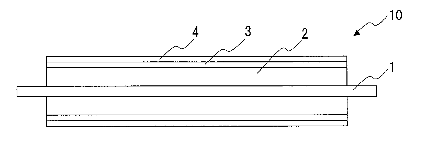
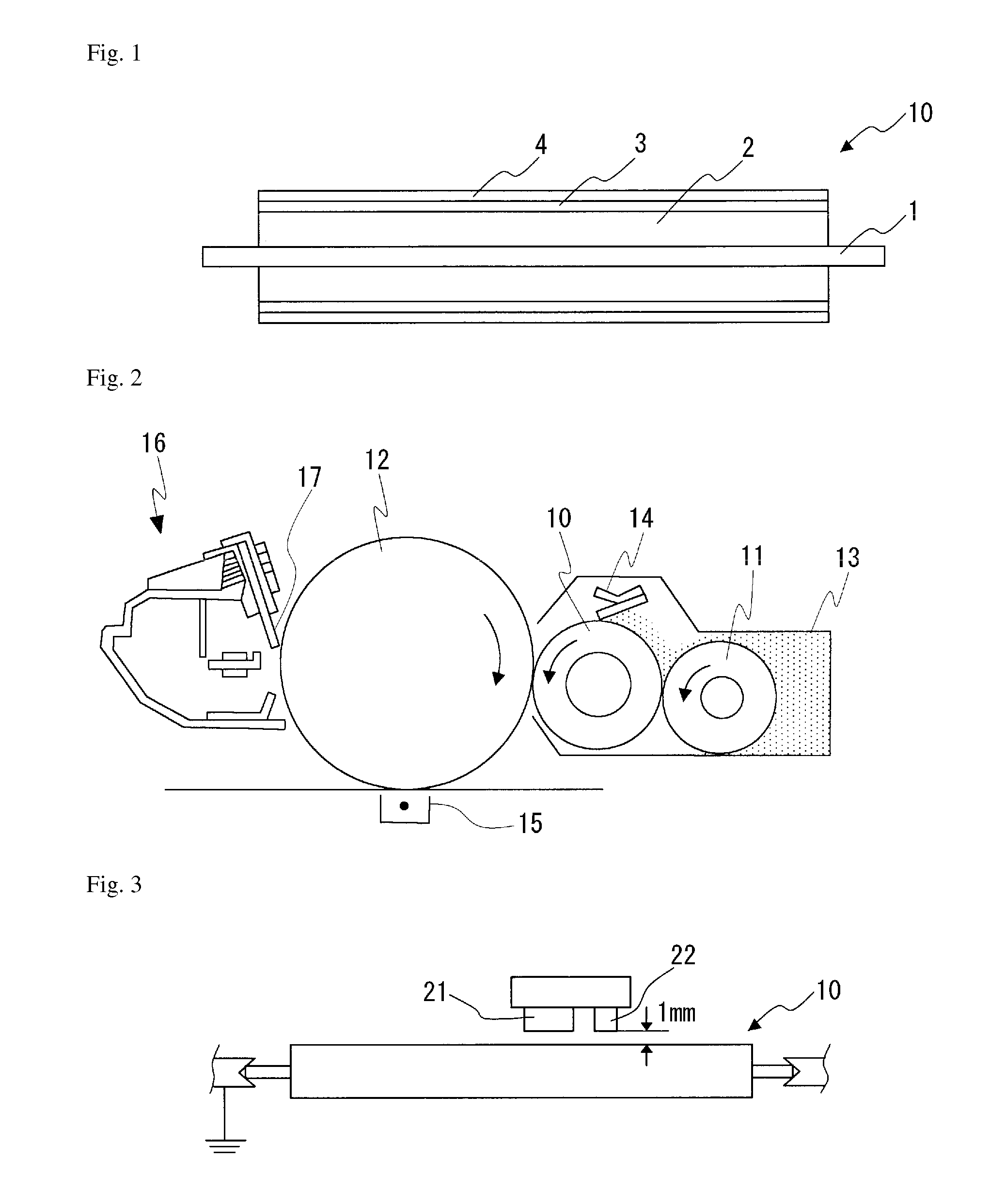
[0044]FIG. 1 illustrates a longitudinal sectional view relating to one example of the developing roller of the present invention. As illustrated, in a developing roller 10 of the present invention, an elastic layer 2, an intermediate layer 3, and a surface layer 4 are successively laminated on the outer periphery of a shaft 1.

[0045]In the present invention, it is important that the surface layer 4 contain a urethane (meth)acrylate oligomer obtained by allowing polybutadiene polyol or hydrogenated polybutadiene polyol, polyisocyanate, and (meth)acrylate having a hydroxyl group to react. By using a highly hydrophobic material, in particular, a polybutadiene polyol as a polyol component of the source of urethane (meth)acrylate oligomer constituting an ultraviolet (UV) curable resin to be used for the surface layer 4, the surface layer 4 can have a high resistance value, in other words, high insulation properties....

second embodiment

[0084]The second embodiment of the present invention will now be described.

[0085]FIG. 1 illustrates a longitudinal sectional view relating to one example of the developing roller of the present invention. As illustrated, a developing roller 10 of the present invention at least comprises an elastic layer 2 on the periphery of a shaft 1, and suitably, an intermediate layer 3 and a surface layer 4 are further successively laminated thereon.

[0086]In the present invention, it is important that elastic layer 2 contains an ultraviolet (UV) curable resin and an ionic conductive agent, and when the surface thereof is electrified by corona discharge at 8 kV from a position 1 mm away from the surface under conditions at a temperature of 32.5° C. and at a humidity of 80% RH, the surface potential 0.4 seconds thereafter is 25 V or higher. By maintaining high the surface potential of the developing roller under high-temperature and high-humidity environment for a certain period of time after elec...

third embodiment

[0125]The third embodiment of the present invention will now be described.

[0126]FIG. 1 illustrates a longitudinal sectional view relating to one example of the developing roller of the present invention. As illustrated, a developing roller 10 of the present invention at least comprises an elastic layer 2 on the periphery of a shaft 1, and suitably an intermediate layer 3 and a surface layer 4 are further successively laminated thereon.

[0127]In the present invention, it is important that the intermediate layer 3 contain a ultraviolet (UV) curable resin, carbon black, a photopolymerization initiator having an absorption coefficient at 254 nm of 2×10⁴ ml / g·cm or higher and a photopolymerization initiator having an absorption coefficient at 365 nm of 4×10² ml / g·cm or higher. When the intermediate layer 3 using a UV curable resin contains a plurality of photopolymerization initiators in each of which a light absorbed by the photopolymerization initiator has a different wavelength, curing...


PUM

PropertyMeasurementUnit
surface potentialaaaaaaaaaa
RHaaaaaaaaaa
temperatureaaaaaaaaaa

Abstract

Provided is a developing roller in which printing quality, in particular, one-dot level fine line printing quality is improved by securing a high resistance value and high surface potential on the surface layer. The elastic roller comprises successively on the outer periphery of a shaft 1 an elastic layer 2, an intermediate layer 3, and a surface layer 4. The surface layer 4 contains a urethane (meth)acrylate oligomer obtained by allowing polybutadiene polyol or hydrogenated polybutadiene polyol, polyisocyanate, and (meth)acrylate having a hydroxyl group to react.

Description

TECHNICAL FIELD[0001]The present invention relates to a developing roller (hereinafter, also simply referred to as “roller”), and more specifically to a developing roller which is used in an image forming process in an image forming apparatus such as a copying machine or a printer.BACKGROUND ART[0002]Conventionally, as a development method in which a non-magnetic one component developer is used as a developer (toner), known is a development method (impression development) in which a toner is provided via a developing roller on an image holding body such as a photoconductor drum on which an electrostatic latent image is held, and the toner is attached to the latent image on the image holding body, thereby visualizing the latent image. Since, in this development method, development is performed by adhering a toner on the latent image on the image holding body by contacting the developing roller on which a toner is held on an image holding body which holds an electrostatic latent image...

Claims


Application Information

Patent Timeline
Patent Type & Authority Patents(United States)
IPC IPC(8): C09D175/16F16C13/00G03G15/08
CPCG03G15/0818F16C13/00G03G15/0808F16C2208/80Y10T428/31551Y10T428/31609F16C2208/00
Inventor OOSAKU, AKIHIDEIMAI, SHOGOFUJISAWA, YUSUKE
Owner BRIDGESTONE CORP
Learn More