
Low voltage bandgap reference circuit

a reference circuit and low-voltage technology, applied in the direction of electric variable regulation, process and machine control, instruments, etc., can solve the problems of failure of the whole failure of the entire electrical function of the bandgap reference circuit, and failure of the differential operation amplifier op. , to achieve the effect of avoiding malfunction and less negative

Active Publication Date: 2015-04-28
CHINGIS TECH CORP
View PDF3 Cites 0 Cited by
  • Summary
  • Abstract
  • Description
  • Claims
  • Application Information

AI Technical Summary

Benefits of technology

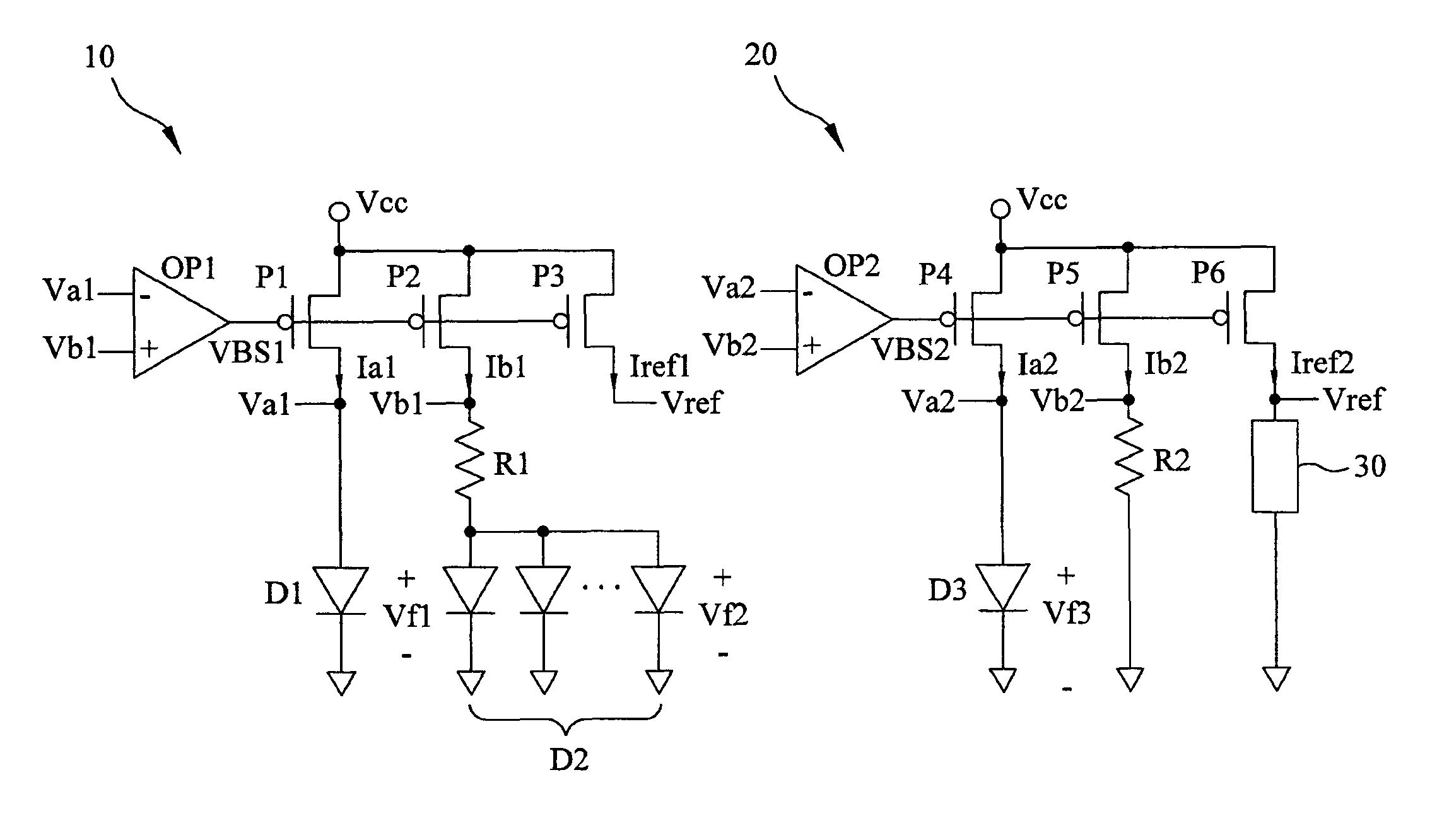
[0042]The primary objective of the present invention is to provide a low voltage bandgap reference circuit for operating at a low voltage and providing a stable reference voltage. The low voltage bandgap reference circuit comprises a positive temperature coefficient circuit unit generating a current with a positive temperature coefficient, a negative temperature coefficient circuit unit generating a current with a negative temperature coefficient, and a load unit through which the currents flow to generate the reference voltage, so as to avoid any influence of the variation of the operating temperature by appropriately cancelling the positive and negative temperature coefficients each other.
[0052]Therefore, it is possible to provide the reference voltage at the low voltage, which suffers less negative effect by the temperature. In particular, the present invention has only one stable operating point such that the operating stability of the whole electrical property is secured, thereby successfully avoiding any malfunction due to the internal operational amplifiers.

Problems solved by technology

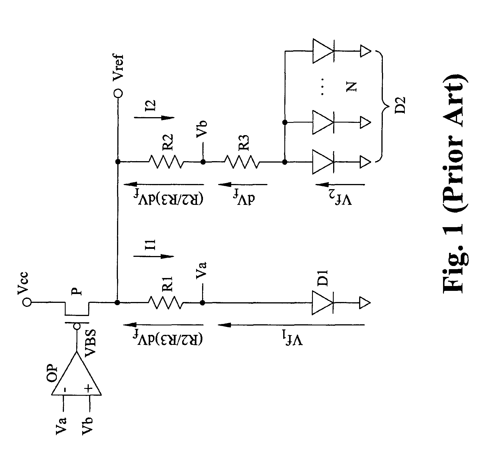
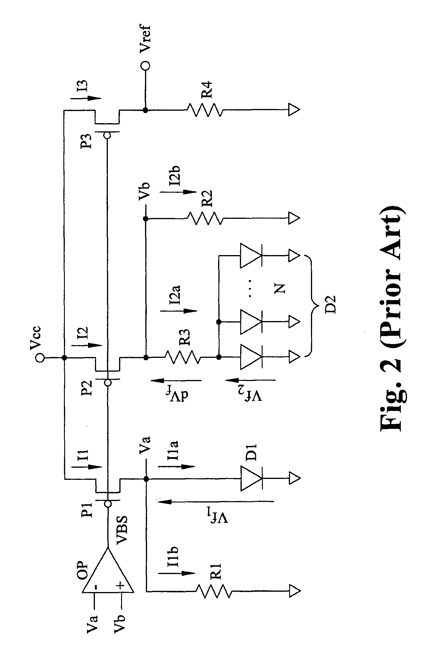
However, one of the shortcomings of the bandgap reference circuit in the prior arts is that the bandgap reference circuit can not normally operate if the power source Vcc is less than the reference Vref, such as 1.27V, because the differential operational amplifier OP and the MOS P do not properly work.
However, the shortcoming of the above bandgap reference circuit is that if R1=R2 and Va and Vb do not attain the corresponding cut-in voltage Vth of the diodes D1 and D2, respectively, at the beginning of starting, I1b>>I1a and I2b>>I1a such that Va is almost equal to Vb, and the differential operational amplifier OP does not normally work.
Thus, start failure results.
Another problem is that the bandgap reference circuit has more than one stable operating point, that is, several intersection points of the inverting input voltage Va and the non-inverting input voltage Vb, as shown in FIG. 3.
Consequently, the whole electrical function of the bandgap reference circuit fails.

Method used


Image

  • Low voltage bandgap reference circuit
  • Low voltage bandgap reference circuit
  • Low voltage bandgap reference circuit

Examples


first embodiment

[0061]Please refer to FIG. 4. As shown in FIG. 4, the low voltage bandgap reference circuit according to the present invention comprises a positive temperature coefficient circuit unit 10, a negative temperature coefficient circuit unit 20 and a load unit 30 to provide a stable reference voltage Vref at the power source Vcc with a low voltage. The positive temperature coefficient circuit unit 10 provides a positive temperature coefficient current Iref1 with the positive temperature coefficient, the negative temperature coefficient circuit unit 20 provides a negative temperature coefficient current Iref2 with the negative temperature coefficient, and the positive and negative temperature coefficient currents Iref1 and Iref2 are combined and flow through the load unit 30. Specifically, the positive and negative temperature coefficients are well designed to cancel each other, and the reference voltage Vref generated at the two ends of the load unit 30 has the net temperature coefficien...

second embodiment

[0081]It can be seen from equation (16) that the low voltage bandgap reference circuit of the second embodiment generates the reference voltage, which can be increased by a magnifying factor simply by changing the ratio of the resistances of the load unit and the second resistor, thereby acquiring the reference voltage Vref by multiplying the magnifying factor and 1.27V.

[0082]For further description of the key features of the low voltage bandgap of the present invention, please refer to FIG. 6 showing the waveform of the low voltage bandgap reference circuit. It should be noted that the waveform is applicable to the first and second embodiments. As shown in FIG. 6, the low voltage bandgap of the present invention has only one stable operating point C, that is, the point at which the first inverting voltage Va1, the first non-inverting voltage Vb1, the second inverting voltage Va2 and the second non-inverting voltage Vb2 coincide. For example, the stable operating point C is 0.76V, l...


PUM


Abstract

A low voltage bandgap reference circuit includes a positive temperature coefficient circuit unit, a negative temperature coefficient circuit unit and a load unit, wherein the positive temperature coefficient circuit unit comprises a first differential operational amplifier, a first, second and third transistor, a first resistor, a first and second diode, and the negative temperature coefficient circuit unit includes a second differential operational amplifier, a fourth, fifth and sixth transistor, a second resistor and a third diode. The low voltage bandgap reference circuit provides a current having a positive temperature coefficient characteristics and a current having a negative temperature coefficient characteristics to flow through the load in order to generate a stable reference voltage less affected by the temperature. Therefore, it avoids the problems of the low voltage bandgap reference circuit that can not be activated at low voltage.

Description

BACKGROUND OF THE INVENTION[0001]1. Field of the Invention[0002]The present invention generally relates to a bandgap reference circuit, which can successfully operate with a low supply-voltage below 1.25V, and more specifically to a bandgap reference circuit having a single stable operating point to avoid startup failure.[0003]2. The Prior Arts[0004]General high performance electronic circuits greatly need a stable reference voltage without suffering from different variations caused by the power source, loading level or operating temperature. For example, the reference voltage can be used as an input signal of a comparator to compare with another internal or external signal. The reference voltage is often generated by a reference circuit with complicated structure so as to block all the inevitable variations due to the power source, loading or temperature.[0005]In the prior arts, electronic manufacturers have successfully developed many reference circuits which can prevent the influ...

Claims


Application Information

Patent Timeline
Patent Type & Authority Patents(United States)
IPC IPC(8): G05F3/16G05F3/30
CPCG05F3/30
Inventor CHANG, CHING-HUNGKUO, CHUN-LUNGWU, CHING-TANGWU, CHUNG-CHENGCHEN, CHUNG-HAO
Owner CHINGIS TECH CORP
Learn More