
Apparatus for assembling a lens module and an image sensor to form a camera module, and a method of assembling the same

a technology of image sensor and camera module, which is applied in the field of apparatus for assembling a lens module and an image sensor to form a camera module, can solve the problems of reducing the operational performance of these camera modules, unable to take into account the respective optical characteristics of the camera module assembly, and conventional open-loop pick-and-place devices cannot provide the required alignment accuracy between the lens modules. , to achieve the effect of accurate alignment of the lens module and high operational performance of the camera modul

Active Publication Date: 2015-04-21
ASMPT SINGAPORE PTE LTD
View PDF46 Cites 5 Cited by
  • Summary
  • Abstract
  • Description
  • Claims
  • Application Information

AI Technical Summary

Benefits of technology

The patent text describes an inspection system that can accurately align the lens module with the image sensor in a camera module. This is achieved by using fiducials on both components, which allows for precise adjustment of the relative position between them. This results in a high-performing camera module with accurate image resolution and auto-focus capabilities. The positioning system uses a gripper to actuate the lens module in six degrees of motion, allowing for precise alignment. Overall, the patent describes a system that ensures the lens module is always in the correct place and can achieve high levels of performance.

Problems solved by technology

Consequently, the operational performance of such camera modules is becoming extremely sensitive to the relative arrangement of the lens module and the image sensor—that is, a slight misalignment of the lens module with respect to the image sensor might result in a significant drop in the operational performance of these camera modules.
Accordingly, conventional open-loop pick-and-place devices can no longer provide the required alignment accuracy between the lens module and image sensor to meet the desired operational performance of these camera modules.
In addition, the assembly of the camera modules does not take into consideration the respective optical characteristics of the lens module and the image sensor.

Method used


Image

  • Apparatus for assembling a lens module and an image sensor to form a camera module, and a method of assembling the same
  • Apparatus for assembling a lens module and an image sensor to form a camera module, and a method of assembling the same
  • Apparatus for assembling a lens module and an image sensor to form a camera module, and a method of assembling the same

Examples


Embodiment Construction

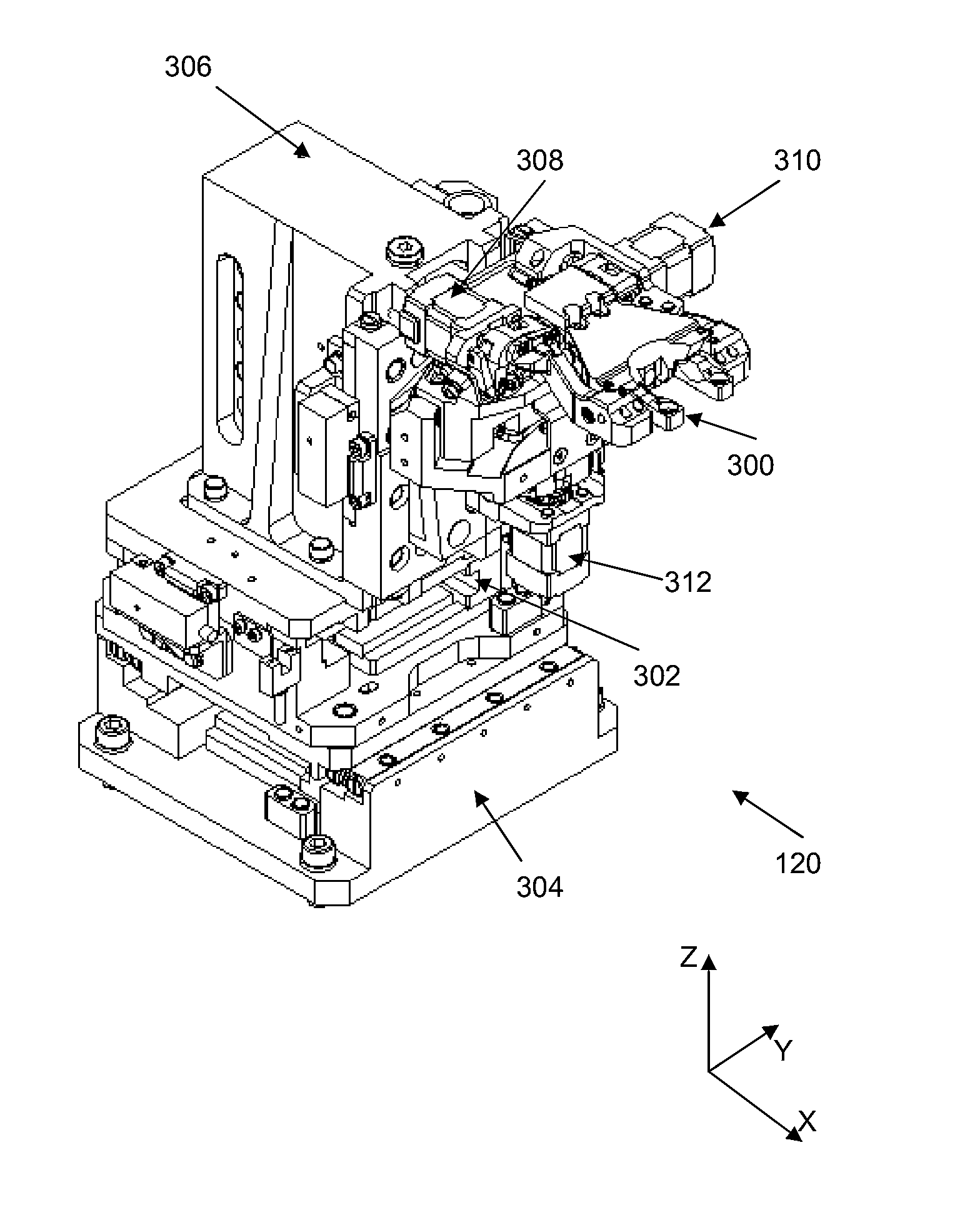
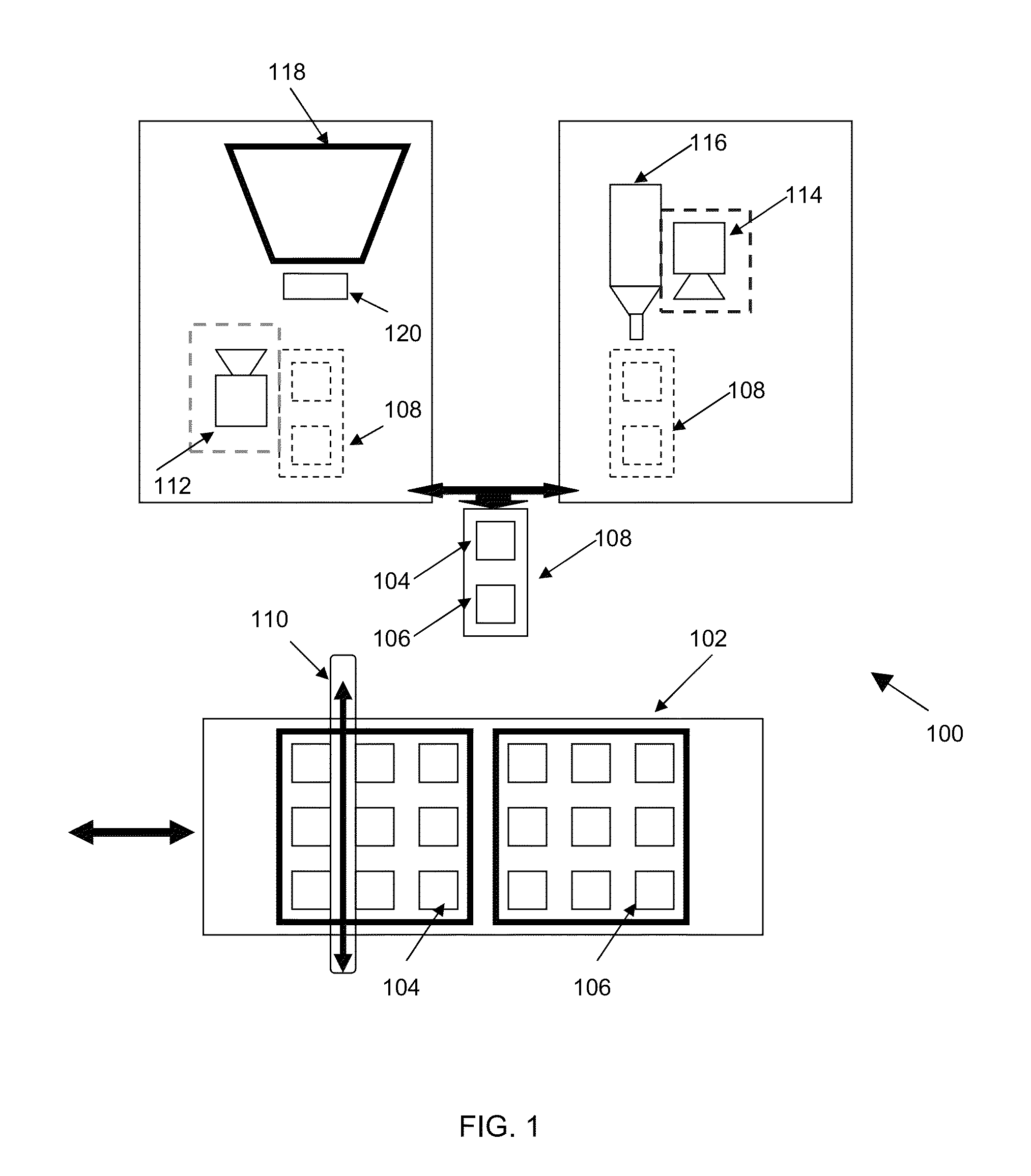
[0030]FIG. 1 is a schematic view of an apparatus 100 according to a first embodiment of the invention. The apparatus 100 comprises: i) an on / offloading device 102 configured to load lens modules 104 and image sensors 106 for assembly to become camera modules; ii) a positioning system (shown in FIG. 1 as a unit transporter 108 on which an image sensor 106 is mountable and an active alignment device 120 having a mechanism for gripping a lens module 104) configured to position the lens module 104 and the image sensor 106 for assembly; iii) a pick arm 110 configured to transfer the lens module 104 and the image sensor 106 to the unit transporter 108; v) a first inspection device (shown in FIG. 1 as an uplook inspection device 112) positioned in a first direction for locating and viewing fiducials on a surface of the lens module 104; vi) a second inspection device (shown in FIG. 1 as a downlook inspection device 114) positioned in a second direction opposite to the first direction for lo...


PUM

PropertyMeasurementUnit
widthaaaaaaaaaa
distanceaaaaaaaaaa
distanceaaaaaaaaaa

Abstract

An apparatus for assembling a lens module and an image sensor to form a camera module. The apparatus comprises i) a positioning system for adjusting a relative arrangement between the lens module and the image sensor; and ii) an inspection system operative to view fiducials of the lens modules and the image sensor. In particular, the positioning system is configured to align the lens module and the image sensor based on a relative alignment of the respective fiducials of the lens module and the image sensor as viewed by the inspection system. A method of assembling a lens module and an image sensor to form a camera module is also disclosed.

Description

FIELD OF THIS INVENTION[0001]This invention relates to an apparatus for assembling a lens module and an image sensor to form a camera module, which is particularly but not exclusively for use in mobile devices such as cell phones, tablets, and laptop computers. The invention also relates to a method of assembling a lens module with an image sensor to form a camera module.BACKGROUND OF THE INVENTION[0002]Operational requirements of camera modules for use in mobile devices such as cell phones, tablets, and laptop computers are rapidly advancing in respect of sharper image resolutions and more sophisticated auto-focus capabilities. At the same time, dimensions of camera modules are also becoming smaller to meet consumer demand. Consequently, the operational performance of such camera modules is becoming extremely sensitive to the relative arrangement of the lens module and the image sensor—that is, a slight misalignment of the lens module with respect to the image sensor might result i...

Claims


Application Information

Patent Timeline
Patent Type & Authority Patents(United States)
IPC IPC(8): B23P21/00B23Q3/00B23Q17/00B23Q17/22
CPCB23Q17/22Y10T29/49769Y10T29/49778Y10T29/4978Y10T29/49895Y10T29/53Y10T29/53022Y10T29/53039Y10T29/53087Y10T29/53091Y10T29/53265G03B17/12
Inventor AU, PO LAMYEUNG, MING LOKTSOI, TUNG YEUNGSUEN, YU LUEN
Owner ASMPT SINGAPORE PTE LTD
Learn More