
Giant-chirp oscillator for use in fiber pulse amplification system

a fiber pulse amplification and giant chirp technology, applied in the direction of active medium shape and construction, laser details, active medium materials, etc., can solve the problems of several stages of amplification, low power oscillator, lossy and costly pulse picker, and the application of solid-state instruments has not yet begun to be replaced by solid-state instruments, etc., to achieve the effect of low repetition rate, low energy of oscillator and low cos

Active Publication Date: 2015-04-14
CORNELL UNIVERSITY
View PDF8 Cites 0 Cited by
  • Summary
  • Abstract
  • Description
  • Claims
  • Application Information

AI Technical Summary

Benefits of technology

[0007]The present invention addresses the foregoing need through provision of a CPA based pulse amplification system that only requires an oscillator, one or more amplifiers and a compressor. This is accomplished through use of a new mode of operation of a fiber oscillator, marked by large pulse energies, large pulse durations and giant pulse chirp. Because of the giant chirp, no stretcher external to the oscillator is needed, as the effect of nonlinear phase accumulation will be small. As a consequence, the energy of the oscillator can be high and can take the place of a stage of pre-amplification. Finally, the oscillator can be designed at very low repetition rates (e.g. less than 10 MHz), thereby erasing the need for a lossy and expensive pulse-picker.
[0008]The key to the oscillator design is that the characteristics of the oscillator components, including the length of a single mode fiber (SMF) and the bandwidth of a spectral filter in the oscillator cavity, are selected so that the oscillator has an inherently lower repetition rate and imparts more than 10 ps2 of group-velocity dispersion to the generated pulses. This results in a chirping of the pulse that is on the order of one or two magnitudes greater than the chirp normally imparted to pulses in previous fiber oscillators. Thus, the phrase “giant chirp” is employed here to describe this key characteristic of the resulting oscillator output pulses. Typically, the high energy giant chirped output pulse will have a duration of 100 ps or more, which eliminates the need for an external pulse stretcher and thus allows the use of increased power levels in the oscillator. The giant chirped pulses can readily be dechirped with any suitable compressor back down to hundreds of femtoseconds (e.g. on the order of 1 ps or less). The result is a short pulse with high energy, achieved without the use of external pulse stretchers and pickers, and with less need for multiple stages of amplification.

Problems solved by technology

Much progress has been made in fiber CPA systems, but to date they have barely begun to supplant solid-state instruments in applications despite their major potential advantages.
The use of a low power oscillator, a pulse stretcher, a lossy and costly pulse picker and several stages of amplification represent costly and inefficient disadvantages to the otherwise desirable CPA based systems.

Method used


Image

  • Giant-chirp oscillator for use in fiber pulse amplification system
  • Giant-chirp oscillator for use in fiber pulse amplification system
  • Giant-chirp oscillator for use in fiber pulse amplification system

Examples


Embodiment Construction

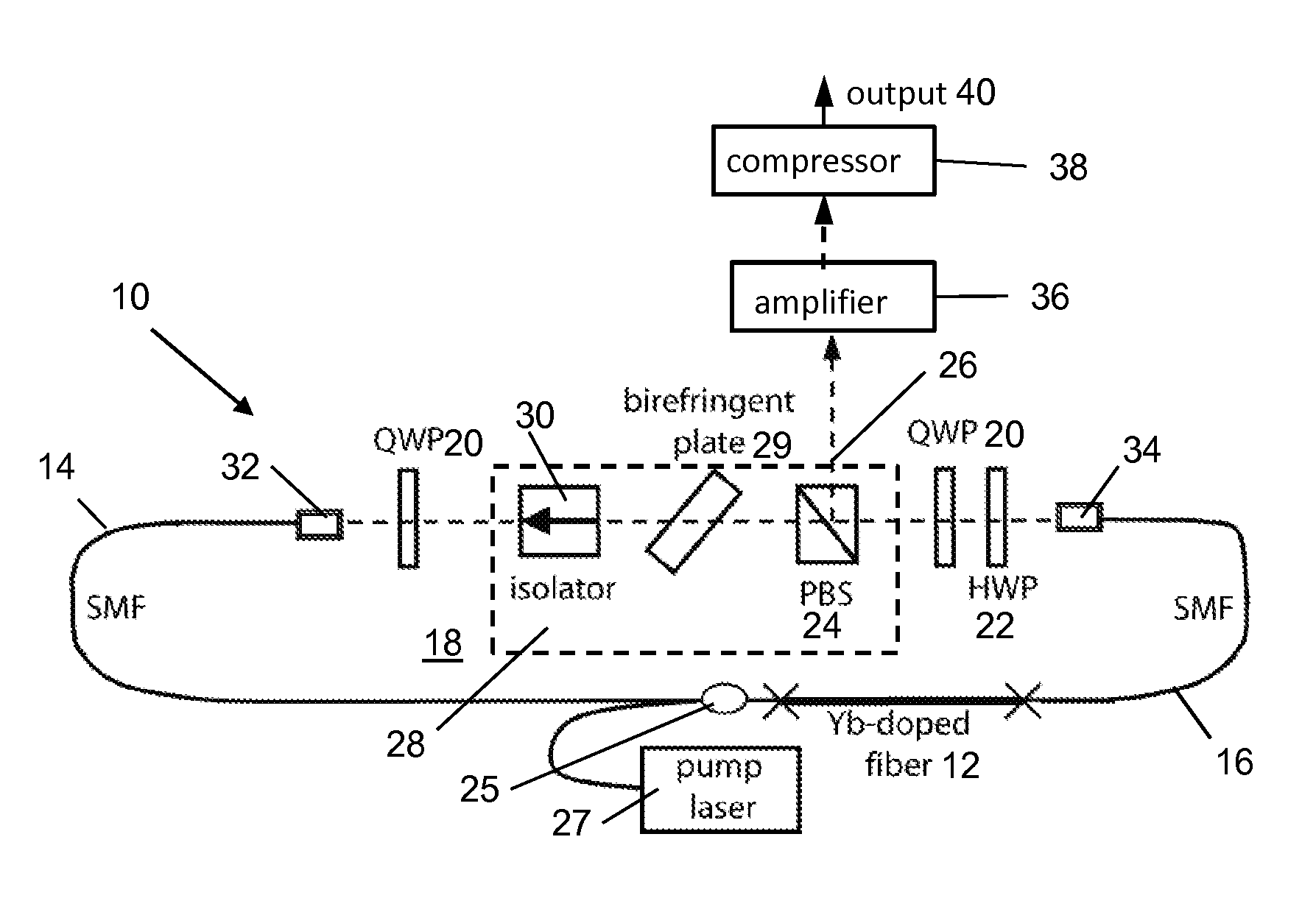
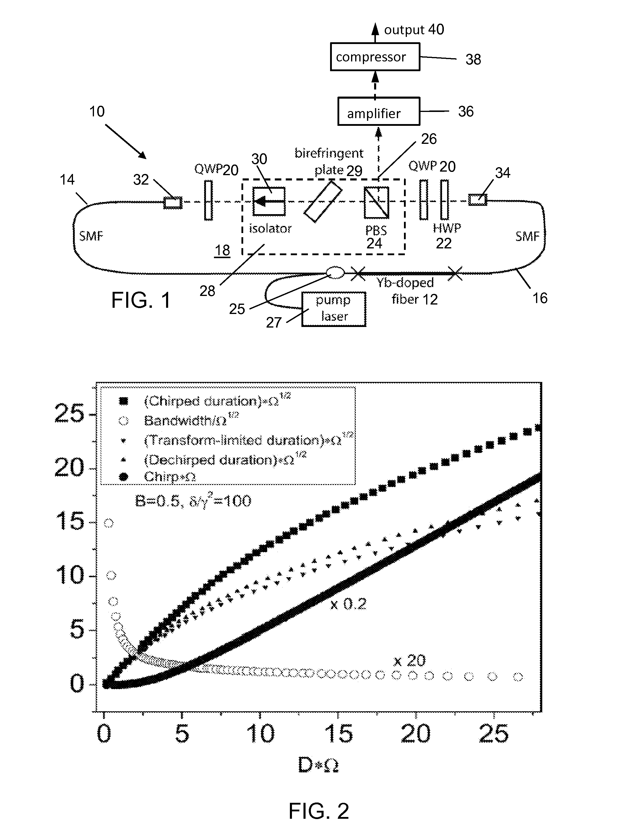
[0015]As noted previously, the major new component of the fiber amplifier system is the oscillator. The details of a first preferred embodiment will first be discussed followed by a discussion of possible variations. A schematic of a fiber oscillator 10 constructed in accordance with a first preferred embodiment of the invention is shown in FIG. 1. The oscillator 10 includes a Yb-doped gain fiber 12, which emits at a wavelength of 1030 nm. It should be noted that many different doping concentrations would suffice for this setup. The oscillator design is conceptually similar to the all-normal-dispersion laser described previously in for example, Published International Application WO 2008 / 105833, which was published on Sep. 4, 2008 and is entitled All-Normal-Dispersion Femtosecond Fiber Laser. However, the fiber segments in the present invention tend to be much longer than in the '833 application and other prior work, to achieve the desired low repetition rate and to introduce normal...


PUM


Abstract

A normal-dispersion fiber laser is operated using parameters in which dissipative solitons exist with remarkably large pulse duration and chirp, along with large pulse energy. A low-repetition-rate oscillator that generates pulses with large and linear chirp can thus replace the standard oscillator, stretcher, pulse-picker and preamplifier in a chirped-pulse fiber amplifier.

Description

GOVERNMENT SPONSORSHIP STATEMENT[0001]The work on this invention was supported by the National Science Foundation under Grant No. ECS-0701680 and the National Institutes of Health under Grant No. EB002019. The Government has certain rights in the invention.BACKGROUND OF THE INVENTION[0002]1. Field of the Invention[0003]The present invention relates in general to a short-pulse amplification technique which employs a laser oscillator that generates pulses with much larger chirps than in known fiber oscillators to reduce the complexity of the overall system design.[0004]2. Description of the Background Art[0005]The generation of femtosecond pulses with energies above 1 μJ from a practical fiber source requires one or more stages of amplification. To avoid excessive nonlinear phase accumulation in the amplifiers, large-mode-area fibers are employed along with chirped-pulse amplification (CPA). A typical fiber CPA system consists of an oscillator, a stretcher, one or more preamplifiers, ...

Claims


Application Information

Patent Timeline
Patent Type & Authority Patents(United States)
IPC IPC(8): H01S3/30H01S3/067H01S3/11H01S3/16
CPCH01S3/067H01S3/1112H01S3/1115H01S3/1618
Inventor RENNINGER, WILLIAM HENRYWISE, FRANK W.
Owner CORNELL UNIVERSITY
Learn More