
Straight tube LED illumination lamp

a technology of led illumination lamp and led light, which is applied in the direction of lighting and heating equipment, instruments, process and machine control, etc., can solve the problems of led illumination lamp damage, straight tube led illumination lamp light instability, etc., and achieve the effect of constant ligh

Inactive Publication Date: 2015-04-07
SODICK CO LTD
View PDF8 Cites 4 Cited by
  • Summary
  • Abstract
  • Description
  • Claims
  • Application Information

AI Technical Summary

Benefits of technology

This design stabilizes the light output, prevents flickering, and extends the lifespan of the lamp by reducing the frequency of switching and managing inrush currents, allowing for easy installation in various fluorescent light fixtures without rewiring.

Problems solved by technology

When the switching on and off of a switching element in a chopper type constant current circuit is frequently repeated, the amount of light of a straight tube LED illumination lamp becomes unstable.
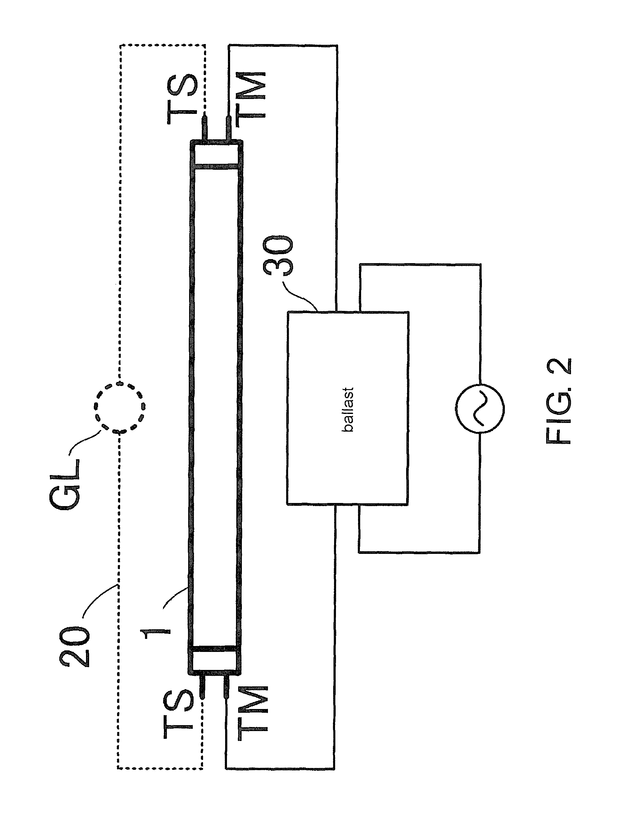
Also, when the straight tube LED illumination lamp is installed in an existing fluorescent light equipment, at the time of startup, a high voltage is applied from a ballast, and an inrush current is applied to an LED illumination lamp, which likely causes damages to the LED illumination lamp.
In view of above, a straight tube LED illumination lamp is provided that is not easy to break down.

Method used


Image

  • Straight tube LED illumination lamp
  • Straight tube LED illumination lamp
  • Straight tube LED illumination lamp

Examples


Embodiment Construction

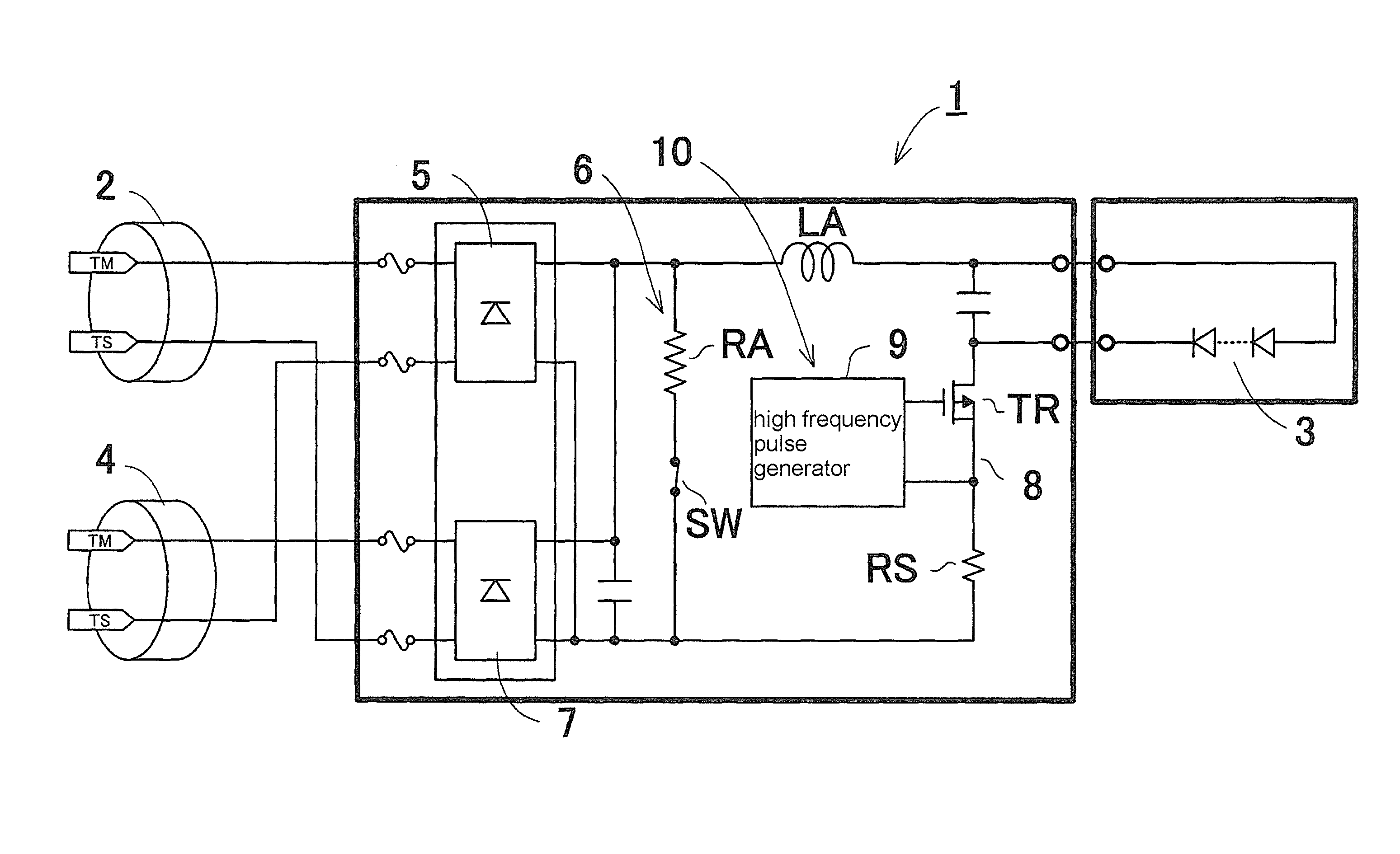
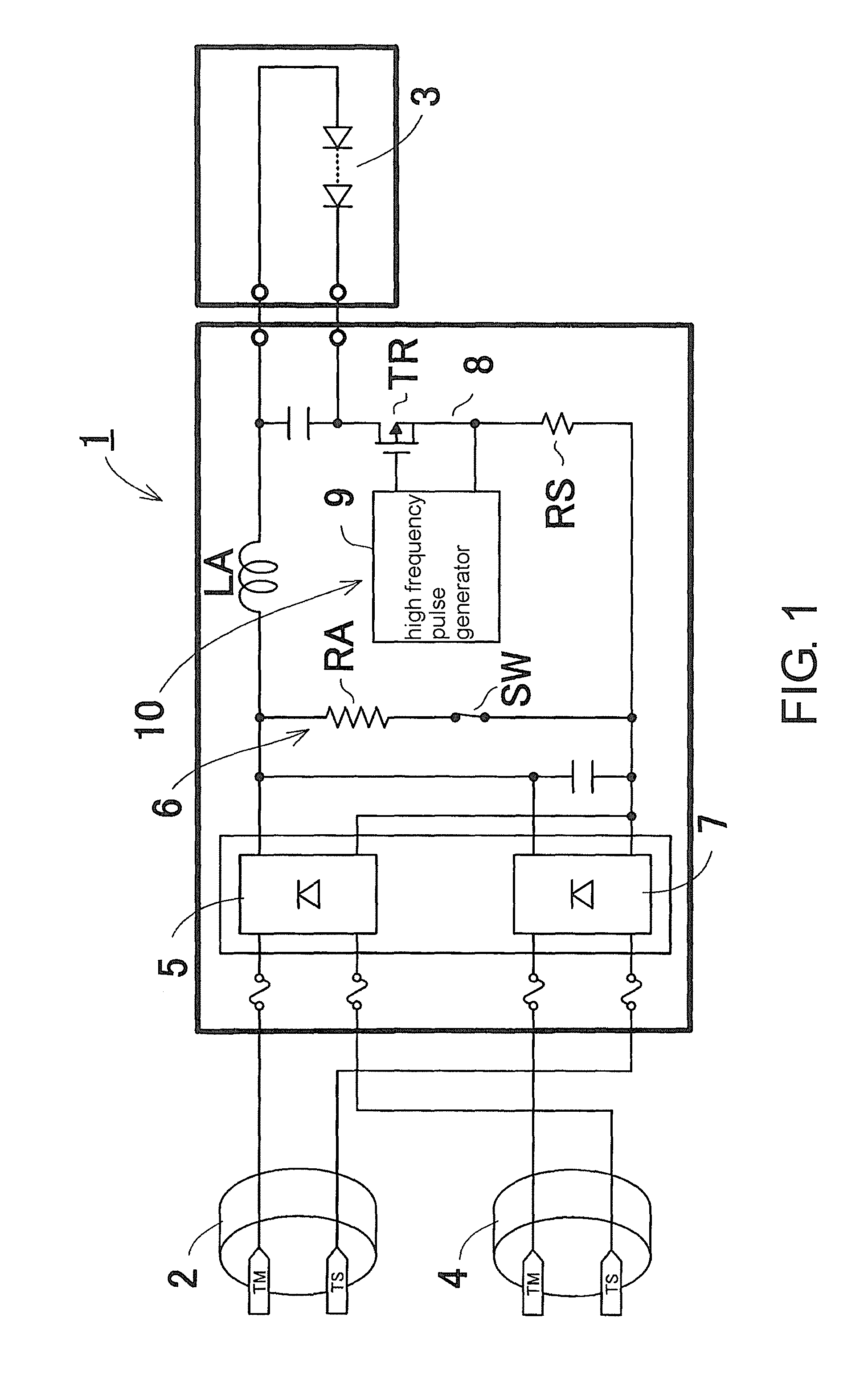
[0022]Referring to figures, a straight tube LED illumination lamp of the present invention is described. Elements that are not directly related to the present invention are omitted from the figures. The same elements are assigned by the same reference numbers. As shown in FIG. 1, the straight tube LED illumination lamp 1 includes a plurality of LED elements 3, a pair of plugs 2, 4, rectifiers 5, 7, a bypass circuit 6 and a chopper type constant current circuit 10. The plugs 2, 4 are respectfully located at both ends of a straight tube. The plurality of LED elements 3, the rectifiers 5, 7, the chopper type constant current circuit 10 and the bypass circuit 6 is stored inside the straight tube.

[0023]The plurality of LED elements 3 is connected to the rectifiers 5, 7 in series. The plurality of LED elements 3 is mutually connected in series. The amount of light emitted by the plurality of LED elements 3 is in accordance to an amount of the direct current provided by the rectifiers 5, 7...


PUM


Abstract

This straight tube LED illumination lamp includes the following: an LED element; a first plug having an input-output terminal and an empty terminal; a second plug having an input-output terminal and an empty terminal; a first rectifier that is connected to the input-output terminal of the first plug and the empty terminal of the second plug in order to convert alternating current to direct current; a second rectifier that is connected to the input-output terminal of the second plug and the empty terminal of the first plug in order to convert alternating current to direct current; and a bypass circuit through which current is flown back from either the first or second rectifier to the other rectifier. The bypass circuit has a current-limiting resistor to prevent the first and second rectifiers from being damaged.

Description

CROSS-REFERENCE TO RELATED APPLICATIONS[0001]This application is a 371 application of an international PCT application serial no. PCT / JP2012 / 056993, filed on Mar. 19, 2012, which claims the priority benefit of Japan application serial no. 2011-060128, filed on Mar. 18, 2011, Japan application serial no. 2011-234782, filed on Oct. 26, 2011, and Japan application serial no. 2011-234784, filed on Oct. 26, 2011. The entirety of each of the above-mentioned patent applications is hereby incorporated by reference herein and made a part of this specification.TECHNICAL FIELD[0002]The present invention relates to a straight tube LED (light-emitting diode) illumination lamp including a rectifier converting an alternating current to a direct current. In particular, the present invention relates to a straight tube LED illumination lamp that can be installed in an existing fluorescent light equipment.BACKGROUND TECHNIQUE[0003]An LED element has been widely used in a signaling light, an electric b...

Claims


Application Information

Patent Timeline
Patent Type & Authority Patents(United States)
IPC IPC(8): H05B37/02H05B33/08F21K99/00H05B44/00
CPCH05B33/0815F21K9/17Y02B20/386F21K9/278H05B45/3725Y02B20/30H05B45/39
Inventor TSUDA, YUKI
Owner SODICK CO LTD
Learn More