Eureka AIR delivers breakthrough ideas for toughest innovation challenges, trusted by R&D personnel around the world.

Wire remote control devices

A technology of remote control and side housing, applied in the field of wired remote control, which can solve the problems of easy formation of scars and cracks

Inactive Publication Date: 2003-01-15
SANYO ELECTRIC CO LTD +1
View PDF0 Cites 0 Cited by
  • Summary
  • Abstract
  • Description
  • Claims
  • Application Information

AI Technical Summary

Problems solved by technology

[0009] In order to avoid the above-mentioned crack K, if the locking part 56 of the remote control main body 1A is loosely fitted to make it easy to open, the combination of the two casings 52 and 53 can be installed during transportation and normal use before installation. In this state, it may be opened. On the contrary, if the locking part 56 is too firmly embedded, there will be problems such as cracks K and easy formation of scars during the disassembly operation.

Method used


Image

  • Wire remote control devices
  • Wire remote control devices
  • Wire remote control devices

Examples


Embodiment Construction

[0024] According to Figure 1- Figure 6 An embodiment of the present invention will be described.

[0025] Figure 6 It is an explanatory diagram showing the relationship between the wired remote controller and the air conditioner in one embodiment of the present invention. Figure 6 Among them, 70 is an air conditioner, and is comprised by the indoor part 71, the outdoor part 72, piping 73, etc. 1 is a wired remote control (hereinafter referred to as the remote control), which is connected to the indoor component 71 through the remote control 74, and the operation of the air conditioner 70 is controlled by the operation of the remote control 1 .

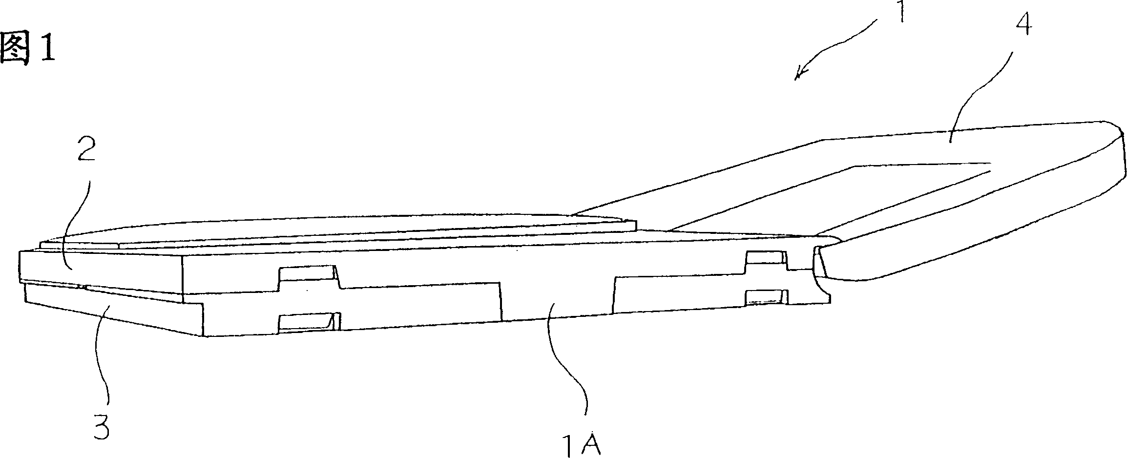
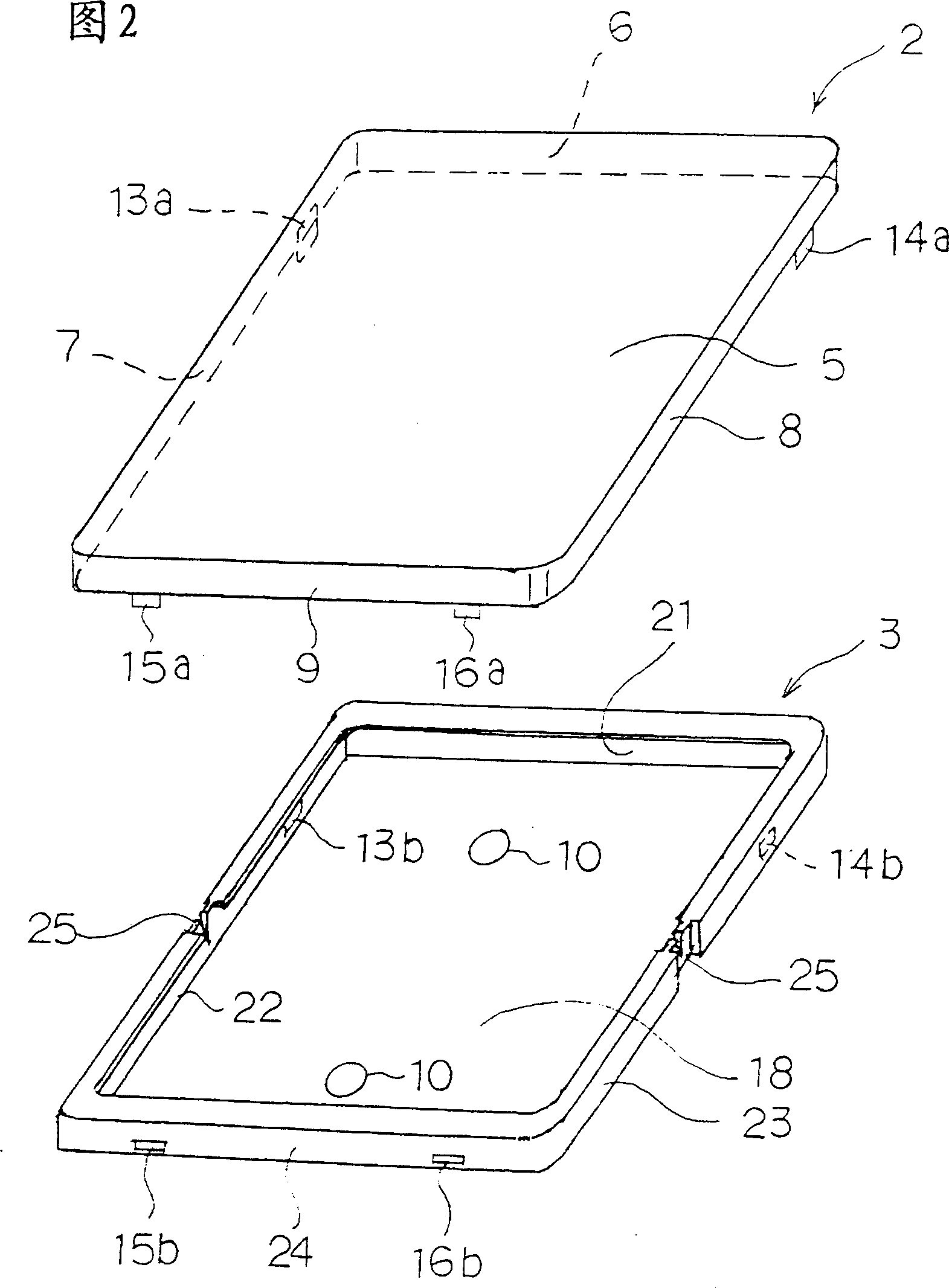
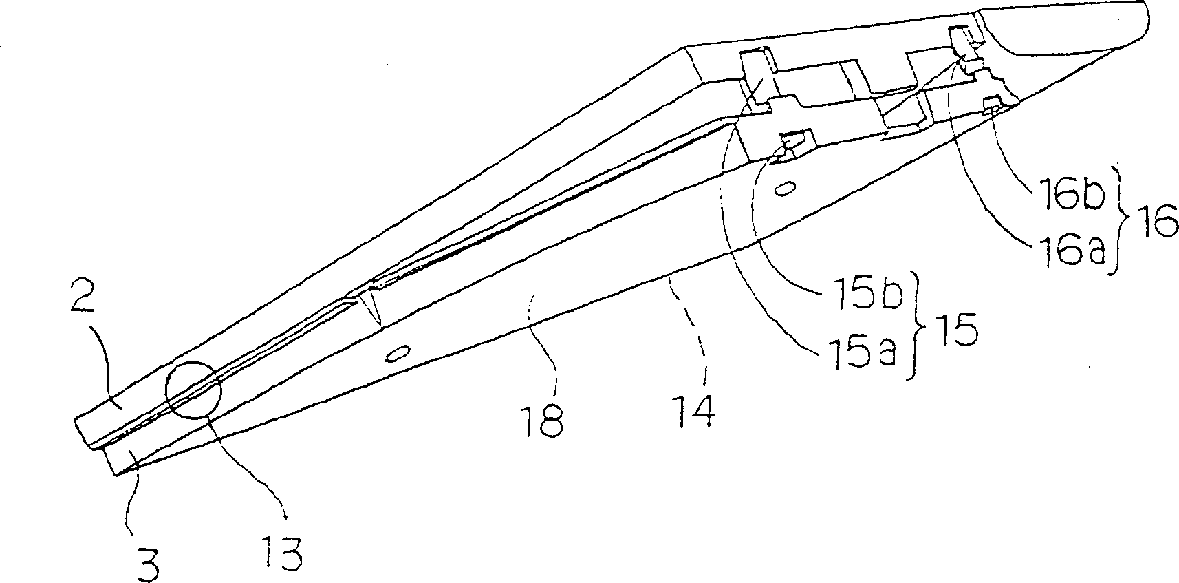
[0026] Fig. 1 is an external perspective view of a wired remote controller of an air conditioner according to an embodiment of the present invention, and Fig. 2 is an exploded perspective view showing an upper case and a lower case of the remote controller in Fig. 1 , image 3 It is a perspective view showing the disassembly oper...


PUM


Abstract

PURPOSE: To provide a wired remote-control hardly developing cracks or flaws, in which disassembling work of a remote-control case is facilitated. CONSTITUTION: The wired remote-control 1 is provided with a lower case 3 having a back board 18 to be attached to a wall of a room surface, and peripheral edge walls 21, 22, 23, 24 formed around the back board 18, and an upper case 2 to be coupled freely removably to the case 3. Slits 26 are formed to peripheral opposing edge-walls 22, 23 in the case 3 so that the lower case 3 can be warped easily.

Description

technical field [0001] The invention relates to a wired remote controller installed on an indoor wall or a column. Background technique [0002] Generally, when an air conditioner is installed, a wired remote controller (hereinafter referred to as a remote controller) used for the air conditioner or the like is mounted on an indoor wall surface, a pillar, or the like. Figure 7, Figure 8 An example of a conventional remote controller is shown. [0003] In Figure 7, Figure 8 Among them, the main body 51A of the remote controller 51 is composed of an upper case 52, a lower case 53, and a door 54 covering the upper case 52, and the two cases 52, 53 are provided with a 52, 53 a plurality of locking parts 56, 56, 57, 57. [0004] On the front side of the upper housing 52, there is a front panel 58 provided with an operation switch for operating the air conditioner, etc., and a back panel 60 is provided on the back panel 60 of the lower housing 53. Mount the remote control mai...

Claims


Application Information

Patent Timeline
IPC IPC(8): F24F1/00F24F11/02F24F13/20H01H9/02H04Q9/00
CPCA63G9/12
Inventor 新里淳诹访一良西田圭二
Owner SANYO ELECTRIC CO LTD
Why Eureka
Eureka Blog
Learn More