Two-stage cooled exhaust gas recirculation system

a technology cooling system, which is applied in the direction engine operation, non-fuel substance addition to fuel, etc., can solve the problems of responding behavior of internal combustion engine and impaired controllability of exhaust gas recirculation ra

Inactive Publication Date: 2015-03-31
DEUTZ AG
View PDF29 Cites 2 Cited by
  • Summary
  • Abstract
  • Description
  • Claims
  • Application Information

AI Technical Summary

Benefits of technology

[0003]It is an object of the present invention to provide a device with which a sufficient quantity of exhaust gas may be recirculated using simple means.
[0004]The present invention provides an exhaust gas recirculation line connected to an exhaust gas collecting line of the exhaust gas system upstream from the turbine of the exhaust gas turbocharger in the direction of flow; an exhaust gas recirculation valve is inserted into the exhaust gas recirculation line upstream from the first stage of the exhaust gas cooler, and a nonreturn valve is installed in a continuation line to the second stage of the exhaust gas cooler. Due to this design, a complex separate compressor for the recirculated gas becomes irrelevant, and due to the use of the nonreturn valve, the pressure pulsations prevailing in the exhaust gas system are utilized to yield a sufficient exhaust gas recirculation rate. An important aspect to achieve the required recirculation rates is to provide the nonreturn valve between the first stage of the exhaust gas cooler and the second stage of the exhaust gas cooler. This configuration utilizes the pulsation of the exhaust gas, which is pronounced at this location, to implement the desired exhaust gas recirculation rate in all operating states and under all operating conditions of the internal combustion engine. Placing the nonreturn valve downstream from the second stage of the exhaust gas cooler would result in lower recirculation rates because the pulsation is definitely degraded due to the available line volume and cooler volume up to this point. In addition, experiments have revealed that due to the mass inertia of the larger exhaust gas recirculation mass in the exhaust gas recirculation system during dynamic operation, the responding behavior of the internal combustion engine and the controllability of the exhaust gas recirculation rate are impaired. Finally, at relatively low temperatures downstream from the second stage of the exhaust gas cooler, the coking tendency of the nonreturn valve increases. These disadvantages are avoided according to the present invention by placing the nonreturn valve between the first stage of the exhaust gas cooler and the second stage of the exhaust gas cooler. Placing the nonreturn valve directly at the outlet of the first stage of the exhaust gas cooler is particularly advantageous here.
[0005]In a refinement of the present invention, the exhaust gas recirculation line to the first stage of the exhaust gas cooler has a multi-flow design including two activated exhaust gas recirculation valves. Together with the multi-flow design of the first stage of the exhaust gas cooler and the continuation line having a nonreturn valve assigned to it, provided in a further embodiment, small volumes which are used to maintain and utilize the pulsations in the exhaust gas stream are implemented up to the nonreturn valves. This effect is further utilized when the exhaust gas collecting line, also having a multi-flow design, is connected to the same number of adjacent cylinders and separate inlets into the turbine of the exhaust gas turbocharger. Pulsations in the exhaust gas stream are therefore continued in a targeted manner to the nonreturn valves.

Problems solved by technology

In addition, experiments have revealed that due to the mass inertia of the larger exhaust gas recirculation mass in the exhaust gas recirculation system during dynamic operation, the responding behavior of the internal combustion engine and the controllability of the exhaust gas recirculation rate are impaired.

Method used


Image

  • Two-stage cooled exhaust gas recirculation system
  • Two-stage cooled exhaust gas recirculation system

Examples


Embodiment Construction

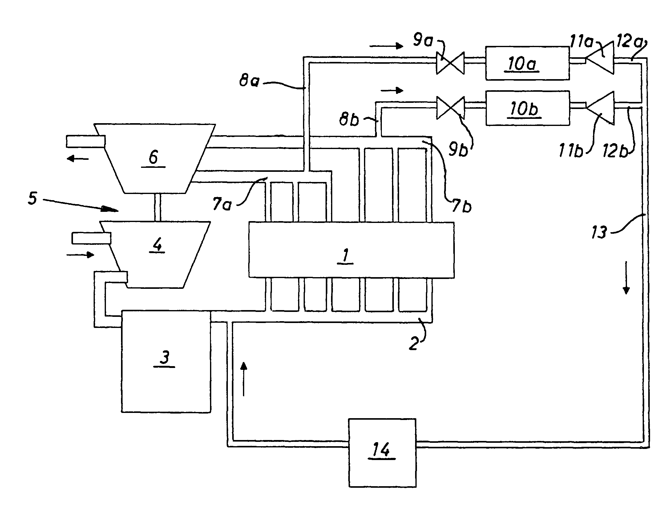
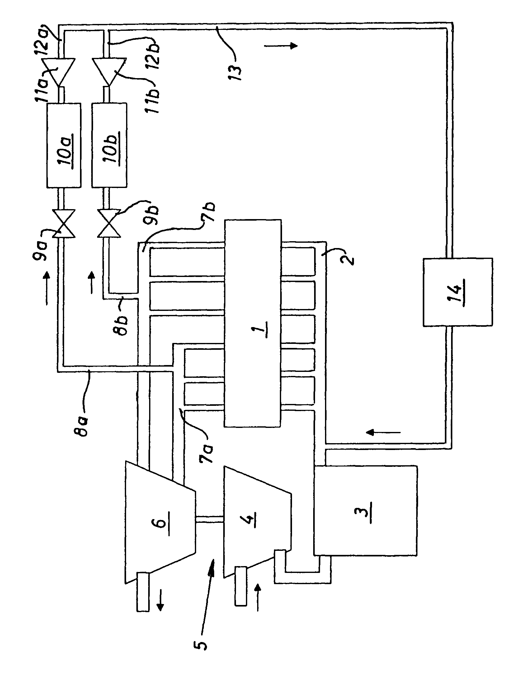
[0008]Additional advantageous embodiments of the present invention may be derived from the description of the drawings, an exemplary embodiment shown in the FIGURE being described in greater detail.

[0009]An internal combustion engine, which is schematically shown in the exemplary embodiment in FIG. 1, is a six-cylinder auto-ignition internal combustion engine in a series design having a fresh gas system and an exhaust gas system. The fresh gas system has a charge air line 2, which connects all the inlet valves of the individual cylinders to one another and to compressor 4 of an exhaust gas turbocharger 5 via a charge air cooler 3. Turbine 6 of exhaust gas turbocharger 5 is driven by the exhaust gases of the internal combustion engine, the exhaust gases being carried from the outlet channels in the cylinder head of internal combustion engine 1 via exhaust gas collecting lines 7a, 7b to the two separate inlets into turbine 6. Two exhaust gas collecting lines 7a, 7b are each assigned t...


PUM


Abstract

A device for cooled recirculation of exhaust gas of an internal combustion engine charged with the aid of an exhaust gas turbocharger, the internal combustion engine having a fresh gas system and an exhaust gas system, which are connected to a two-stage exhaust gas cooler via an exhaust gas recirculation line. A device by way of which a sufficient amount of exhaust gas may be recirculated by simple means is provided. This is achieved in that exhaust gas recirculation line 8a, 8b is connected to an exhaust gas collecting line 7a, 7b of the exhaust gas system upstream from turbine 6 of exhaust gas turbocharger 5 in the direction of flow, an exhaust gas recirculation valve 9a, 9b being connected upstream from first stage 10a, 10b of the exhaust gas cooler in exhaust gas recirculation line 8a, 8b, and a nonreturn valve 11a, 11b is inserted into a continuation line 12a, 12b leading to the second stage of the exhaust gas cooler.

Description

[0001]The present invention relates to a device for cooled recirculation of exhaust gas of an internal combustion engine charged with the aid of an exhaust gas turbocharger, the internal combustion engine having a fresh gas system and an exhaust gas system, which are connected to a two-stage exhaust gas cooler via an exhaust gas recirculation line.BACKGROUND[0002]Such a device is known from DE 10 2005 017 905 A1. In the system presented in this document, an exhaust gas recirculation line branches off from the exhaust gas line downstream from the turbine of an exhaust gas turbocharger, and the exhaust gas to be recirculated is raised to a higher pressure level by a separate compressor and then introduced into the fresh air line downstream from a charge air cooler.SUMMARY OF THE INVENTION[0003]It is an object of the present invention to provide a device with which a sufficient quantity of exhaust gas may be recirculated using simple means.[0004]The present invention provides an exhaus...

Claims


Application Information

Patent Timeline
Patent Type & Authority Patents(United States)
IPC IPC(8): F02B47/08F02M25/07
CPCF02M25/0713F02M25/0707F02M25/0732F02M25/0751F02M25/0744F02M25/0745F02M25/0749F02M25/0779Y02T10/121F02M26/39F02M26/43F02M26/59F02M26/05F02M26/10F02M26/24F02M26/38F02M26/44
Inventor HUELSMANN, BERND
Owner DEUTZ AG
Why Eureka
Try Eureka