
Combustor with a lean pre-nozzle fuel injection system

a fuel injection system and combustion chamber technology, applied in the ignition of turbine/propulsion engines, engine starters, lighting and heating apparatus, etc., can solve the problems of high nitrogen oxide levels, other types, operational problems

Active Publication Date: 2015-03-31
GENERAL ELECTRIC CO
View PDF29 Cites 14 Cited by
  • Summary
  • Abstract
  • Description
  • Claims
  • Application Information

AI Technical Summary

Benefits of technology

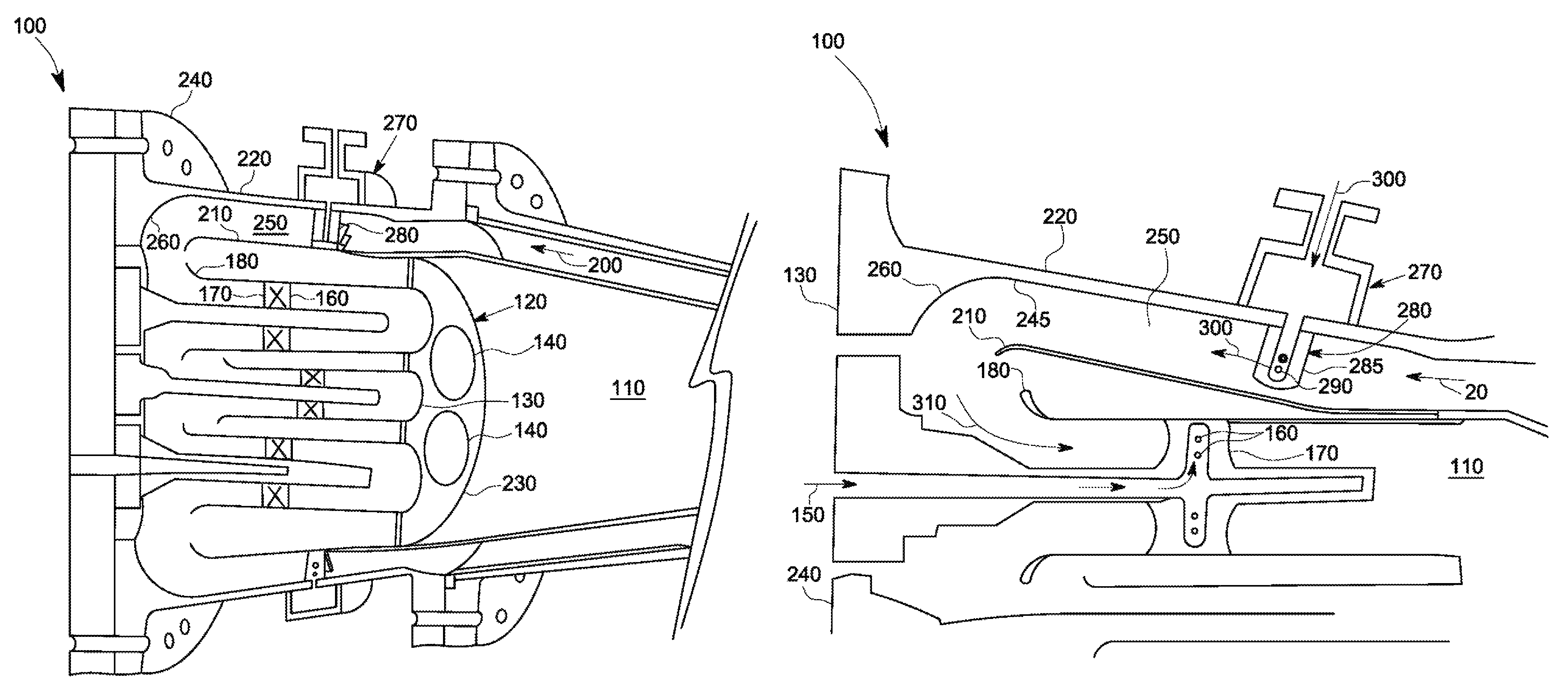
The present patent application provides a combustor for combusting a flow of fuel and a flow of air. The combustor includes a number of fuel nozzles, a lean pre-nozzle fuel injection system positioned upstream of the fuel nozzles, and a premixing annulus positioned between the fuel nozzles and the lean pre-nozzle fuel injection system to premix the flow of fuel and the flow of air. The premixing annulus may expand in the direction of the fuel nozzles. The technical effect is to provide improved combustion efficiency and reduced emissions in combustion engines, by premixing the fuel and air in a controlled manner to create a well-controlled mixture that is injected into the combustion chamber.

Problems solved by technology

Higher combustion stream temperatures, however, may produce higher levels of nitrogen oxide (“NOx”) and other types of emissions that may be subject to both federal and state regulation in the United States and also subject to similar regulations abroad.
Such premixing tends to reduce overall combustion temperatures and, hence, NOx emissions and the like.
Premixing, however, may present several operational issues such as flame holding, flashback, auto-ignition, and the like.
These issues may be a particular concern with the use of highly reactive fuels.
Any type of fuel rich pocket thus may sustain a flame and cause damage to the combustor.
Other premixing issues may be due to irregularities in the fuel flows and the air flows.

Method used


Image

  • Combustor with a lean pre-nozzle fuel injection system
  • Combustor with a lean pre-nozzle fuel injection system
  • Combustor with a lean pre-nozzle fuel injection system

Examples


Embodiment Construction

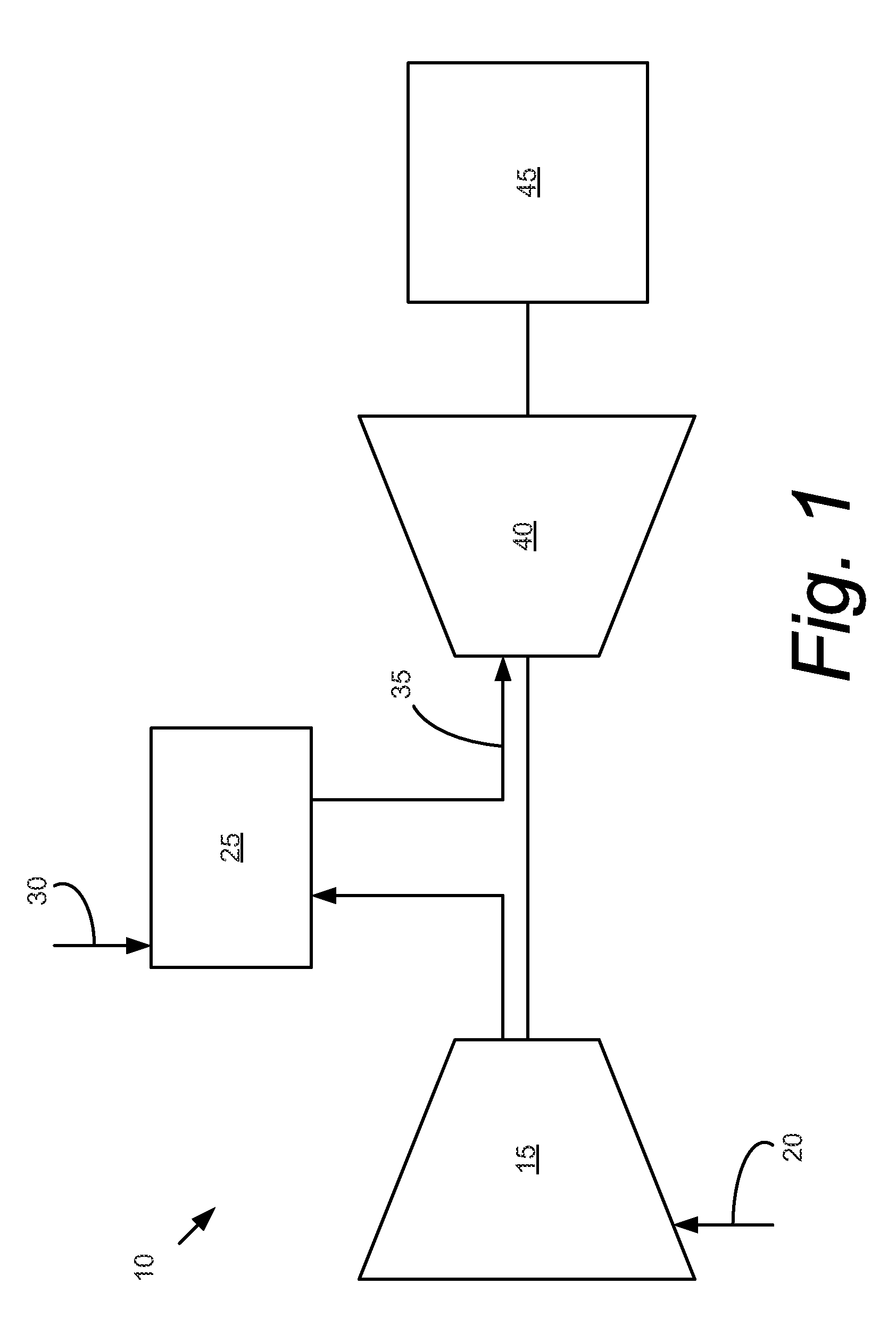
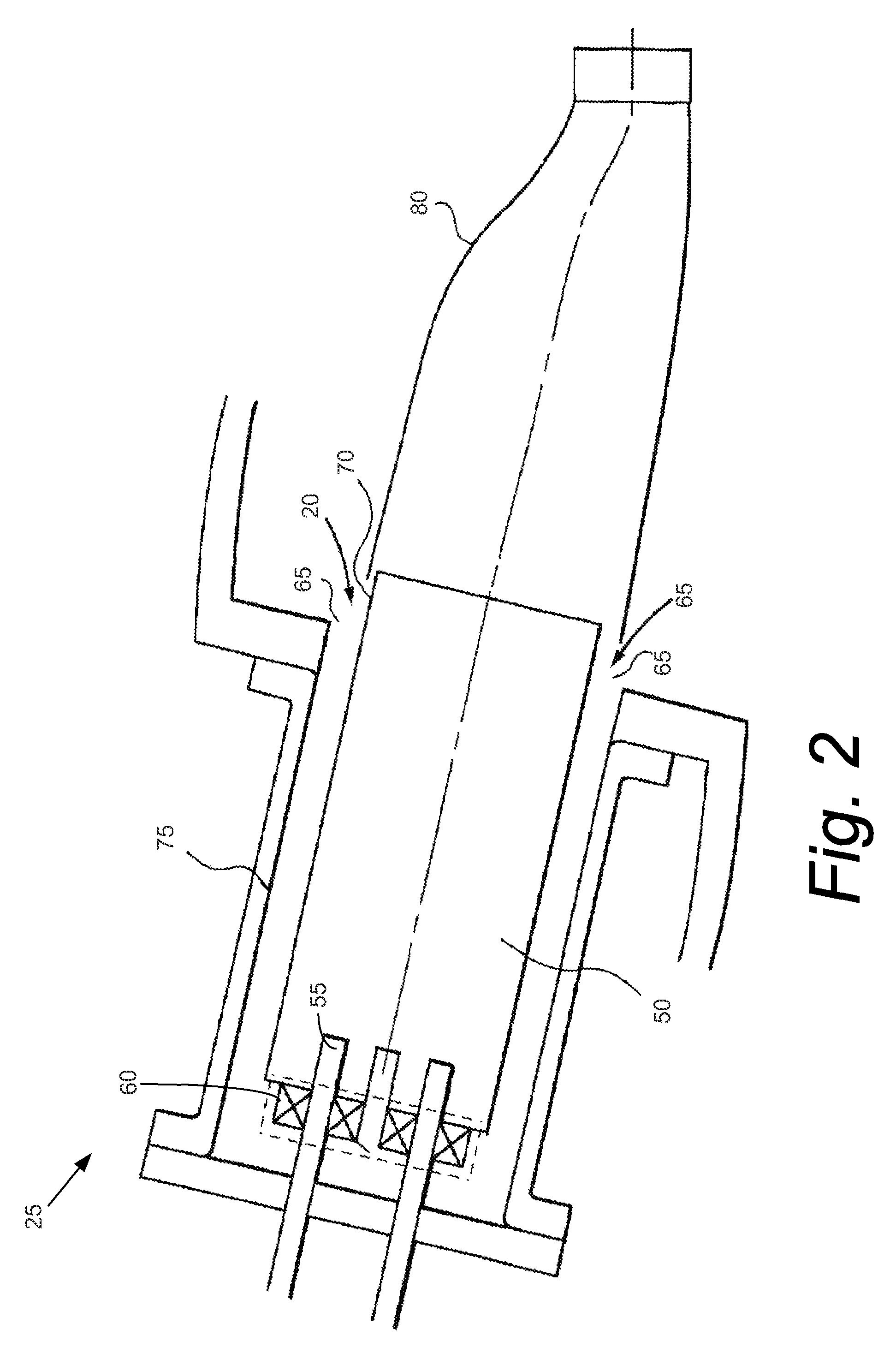
[0014]Referring now to the drawings, in which like numerals refer to like elements throughout the several views, FIG. 1 shows a schematic view of gas turbine engine 10 as may be described herein. The gas turbine engine 10 may include a compressor 15. The compressor 15 compresses an incoming flow of air 20. The compressor delivers the compressed flow of air 20 to a combustor 25. The combustor 25 mixes the compressed flow of air 20 with a compressed flow of fuel 30 and ignites the mixture to create a flow of combustion gases 35. Although only a single combustor 25 is shown, the gas turbine engine 10 may include any number of combustors 25. The flow of combustion gases 35 is in turn delivered to a turbine 40. The flow of combustion gases 35 drives the turbine 40 so as to produce mechanical work. The mechanical work produced in the turbine 40 drives the compressor 15 and an external load 45 such as an electrical generator and the like.

[0015]The gas turbine engine 10 may use natural gas,...


PUM


Abstract

The present application provides for a combustor for combusting a flow of fuel and a flow of air. The combustor may include a number of fuel nozzles, a lean pre-nozzle fuel injection system positioned upstream of the fuel nozzles, and a premixing annulus positioned between the fuel nozzles and the lean pre-nozzle fuel injection system to premix the flow of fuel and the flow of air.

Description

TECHNICAL FIELD[0001]The present application relates generally to gas turbine engines and more particularly relates to a combustor with a lean pre-nozzle fuel injection system for mixing fuel and air upstream of the fuel nozzles.BACKGROUND OF THE INVENTION[0002]In a gas turbine engine, operational efficiency generally increases as the temperature of the combustion stream increases. Higher combustion stream temperatures, however, may produce higher levels of nitrogen oxide (“NOx”) and other types of emissions that may be subject to both federal and state regulation in the United States and also subject to similar regulations abroad. A balancing act thus exists between operating the gas turbine engine in an efficient temperature range while also ensuring that the output of NOx and other types of regulated emissions remain below the mandated levels.[0003]Several types of known gas turbine engine designs, such as those using Dry Low NOx (“DLN”) combustors, generally premix the fuel flow...

Claims


Application Information

Patent Timeline
Patent Type & Authority Patents(United States)
IPC IPC(8): F02C1/00F02G3/00F23R3/28F23R3/36
CPCF23R3/286F23R3/36F23C2900/07001F23C2900/9901
Inventor HUGHES, MICHAEL JOHNBERRY, JONATHAN DWIGHTSTEWART, JASON THURMANVALEEV, ALMAZWU, CHUNYANG
Owner GENERAL ELECTRIC CO
Learn More