Tile and tile assembly for a roof

a technology for roofs and tiles, applied in the field of roof tiles, can solve the problems of reducing the life of roofs, eddies and turbulence with increased wind resistance, and prior art tile types failing to compensate for structural variations of tiles, so as to facilitate the redirection of water, simplify the installation of tiles, and achieve some freedom of installation

Active Publication Date: 2015-03-31
KRAMER KURT JOSEPH
View PDF50 Cites 3 Cited by
  • Summary
  • Abstract
  • Description
  • Claims
  • Application Information

AI Technical Summary

Benefits of technology

[0016]At the lateral extents of each pattern within each tile, the edges of the upper and lower flanges and of the main surface blend together to form an inflection plane which is perpendicular to the main surface. Patterns within a tile which are laterally spaced next to each other have inflection planes matching along their respective lateral extents, and fabricated so the patterns are contiguous and continuous with a small transition between the inflection edges integrated as needed and appropriate for the manufacturing processes used (FIG. 7A).
[0017]To the extent the lower flange apex of the upper tile overlaps and covers the inflection edges of the center tiles, it is difficult for water to enter and pass through the line of intersection of the two abutting edges. Further, under each center tile, the upturned flanges at the upper end of the bottom tile are adapted to serve as a catch basin pan beneath the inflection edges of the two center tiles to collect any water that may pass through. The water can then be directed over the outer surface of the bottom tile through a gap or cutaway space at the lowest point of the inflection edges. In one aspect, the lower flange apex of the upper tile does not necessarily overlap the entire inflection edge intersection of the two center tiles, as at least part of the streamlined lower flanges are directly exposed to rain. Spanning any gap between the abutting adjacent center tile infection edges and redirecting water which has passed through back out onto the main surface, is accomplished through the use of a lower rain gusset (FIGS. 8 A & B). The lower rain gusset fits under the lower portions of the inflection edges of two adjacent center tiles to provide additional protection against the ingress of water through the intersection of the inflection edges. The lower gusset keeps the inflection edges of the center tiles close together and in alignment. To facilitate the redirection of water out from the gusset to the exposed main tile surface, the lower inflection edges are cut away partially at and near the ends. This can be accomplished by rounding the ends of the lower inflection edges. This open area is also useful for tiles which do not use the lower gusset. At each pattern to pattern adjacent lower tile junction, an opening at the bottom of the abutting lower flanges allows water behind the lower flanges to be directed out and over the outer surfaces of tiles.
[0018]One further embodiment of the invention resides in a supplemental upper rain gusset which can be used, as an alternative embodiment (FIG. 8 C). The upper rain gusset fits over at least the upper portions of the inflection edges of two adjacent center tiles to provide additional protection against ingress of water through the adjacent inflection edges to the roof and to the tiles below it.
[0019]In a further embodiment, at and along the inflection edges of the tiles, a lip and pan arrangement can be added to the two side by side tile inflection edges to limit water passing through the adjacent tiles and to provide a drainage channel (FIG. 7 A, FIG. 7 B and FIG. 17). This lip and pan arrangement can be formed to allow the tiles to snap together during installation. The lip and pan act as a blockage to water falling between the inflection edges and a channel to redirect water in the area to the outer tile surfaces. In some configurations of the lip and pan, additional separation between tiles is needed to accommodate the lip and pan arrangement, and this separation must be matched and added to the transitions between patterns within each tile. In addition, to accommodate the separation, the lower apex tip of the top tile must be rounded to allow for the additional separation between center tiles or the apex will have to be placed lower in relation to the center tiles, and will overlap more.
[0020]In still another embodiment, the upper flange of each tile pattern in the infection edge region is notched to accommodate the passage of a fastener so as to simplify the installation of the tiles. One type of fastener is a two headed nail, each having a shaft and a head which extends oppositely in two directions to overlap the upper edges of two adjacent tiles or patterns (FIG. 7 A &FIG. 7 B). When the fastener is driven into place, its head region overlaps and grips the two upper adjacent flanges in the notched regions to hold the flanges and tile in place. The notch, which is oversize in relation to the size of the nail shaft, permits the fastener to have some freedom of installation. This freedom, aided by the infection edge itself which accommodates some misalignment of the adjacent edges of two center tiles, provides for an installation which is forgiving of structural variations in the roof support, manufacturing tolerances of tiles, and accommodates some carelessness on the part of the installer in positioning the fasteners when driving them into the underlying layer or lath. Laths are used for the tile assembly to provide support, less penetrations of the supporting roof structure, and for easier fastening (FIG. 18).
[0021]In one aspect, the fasteners may include features, such as a lining underneath the fastener head to absorb shocks and to hold the upper and lower abutting flanges together.

Problems solved by technology

While tiles of the prior art type, as previously described, are generally satisfactory, certain disadvantages are associated with such a structure.
The essentially perpendicular flange relationships would tend to interfere with laminar flow of wind over the roof, which creates eddies and turbulence with increased wind resistance.
In general, wind resistance is undesirable in a roofing system due to increases in wind noise and, in severe wind conditions over time, can contribute to the earlier loosening of tiles and reduction of roof life.
In addition, this prior art type of tile fails to compensate for structural variations of the tiles due to imprecise manufacturing techniques involved in tile making.
These structural variations of the tiles can lead to difficulties in fitting tiles together due to interference fits and instances of roofers installing tiles imprecisely on the roof laths such that they are to some degree misaligned.
Sometimes, the roof deck may not be perfectly flat which contributes to the alignment problem.
Another problem that can arise with tiles of this character is in connection with water as it falls and runs down the exposed surfaces of the tiles.
Labor cost is a significant portion of the total cost of a new roof or roof replacement.

Method used


Image

  • Tile and tile assembly for a roof
  • Tile and tile assembly for a roof
  • Tile and tile assembly for a roof

Examples


Embodiment Construction

[0069]Reference will now be made to the drawings wherein like numerals refer to like parts throughout.

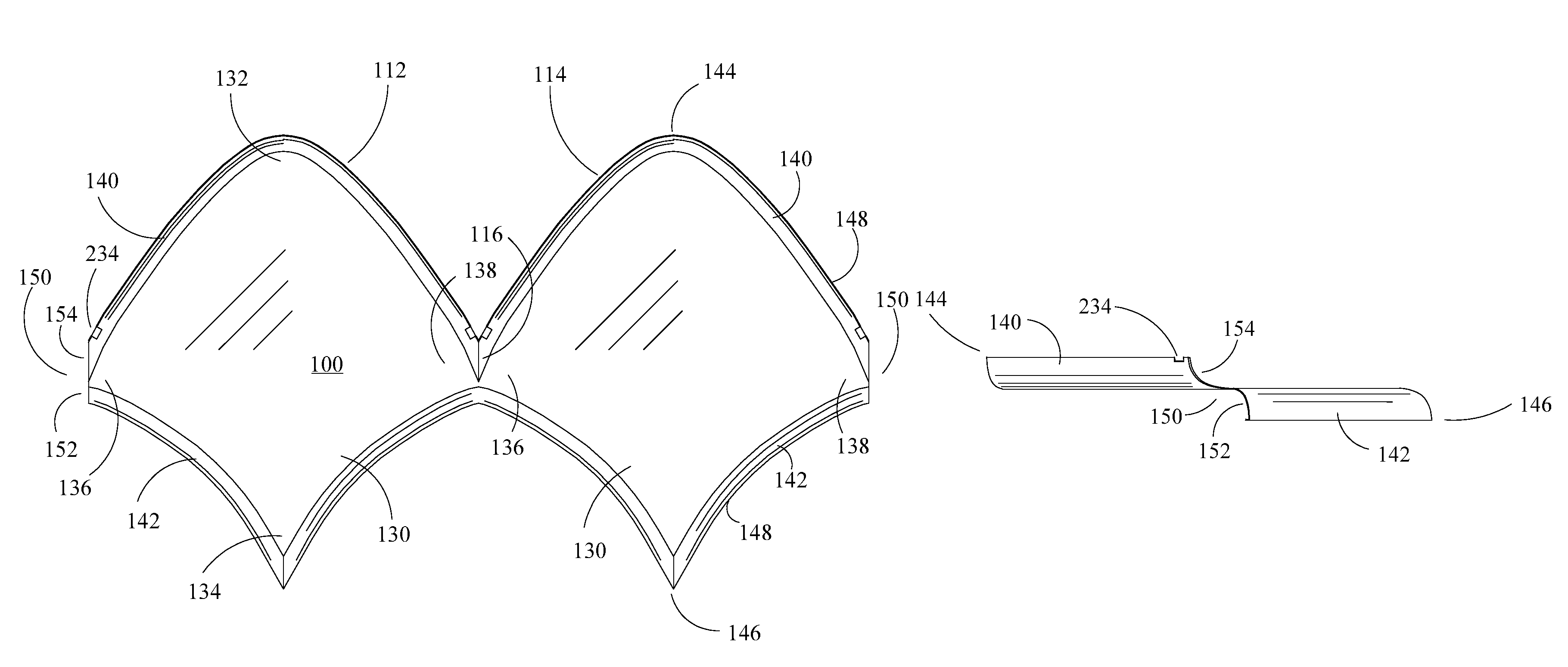
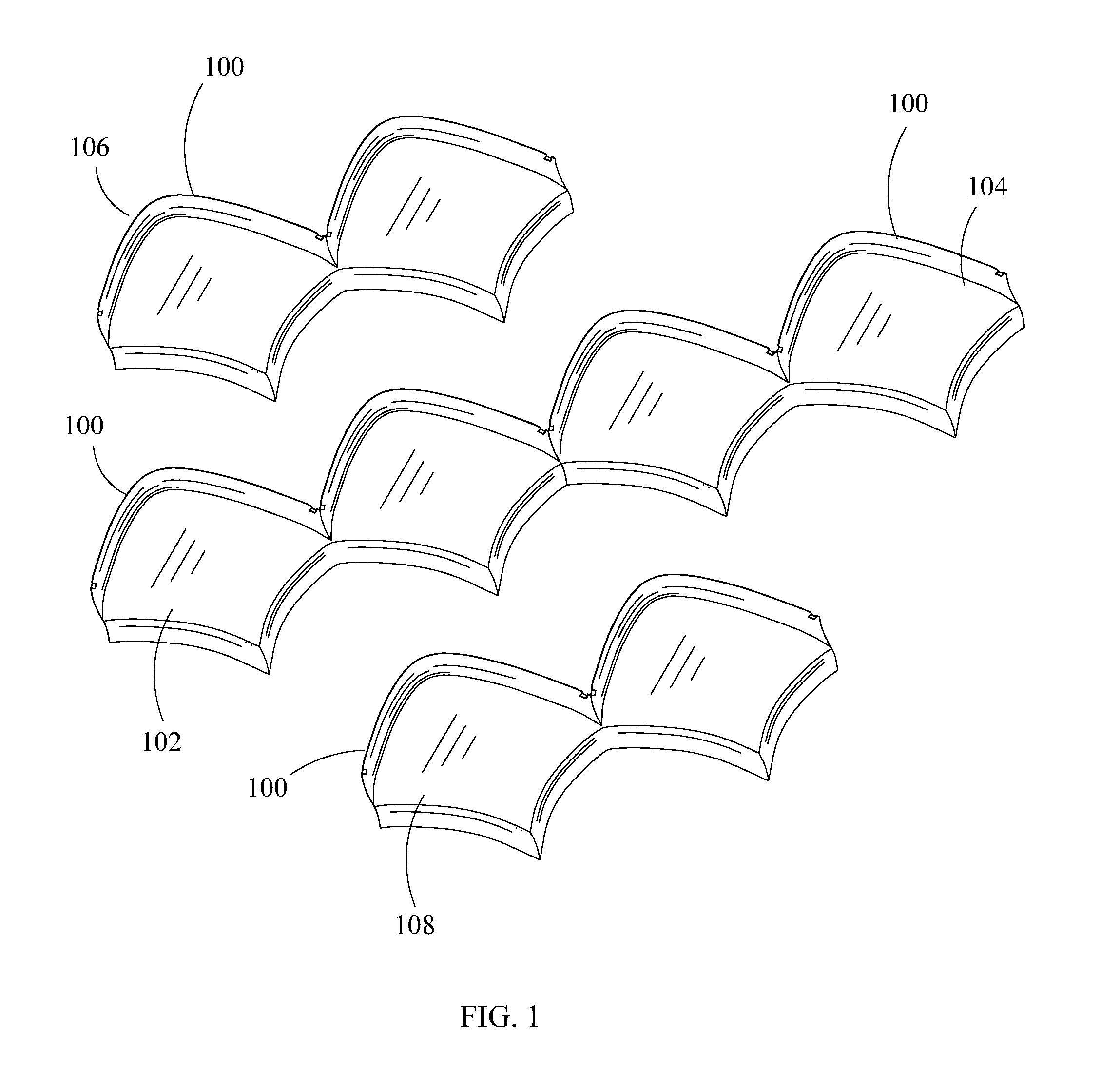
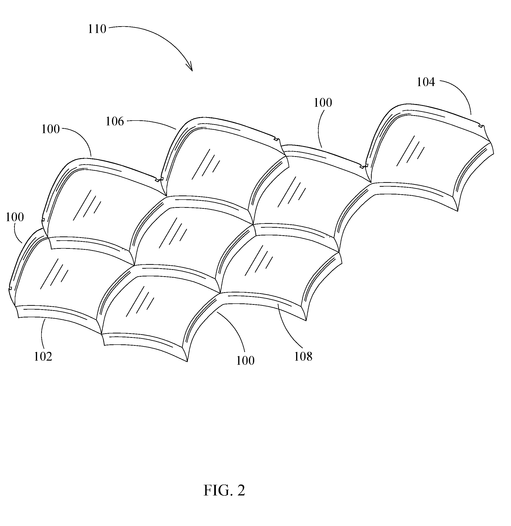
[0070]FIG. 1 illustrates one embodiment of a plurality of diamond patterned tiles 100 for assembly. FIG. 2 illustrates one embodiment of a tile assembly 110 having at least four tiles 100 grouped together in an assembly. FIG. 3 illustrates a plurality of tiles 100 and tile assemblies 110 linked together with adjacent tile assemblies 110 to form a roof 120 of a structure. Roof 120 extends in downwardly inclined planes from either side of a roof line 122. FIG. 4 illustrates a top view of tile 100, FIG. 5 illustrates a bottom view of tile 100 and FIG. 6 illustrates a side view of tile 100. In the following description, a single tile assembly 110 is described, but it will be understood that the flanges of each tile 100 hook over and interlock with the flanges of adjacent tiles 100 in a repeating arrangement of tile assemblies 110 to form roof 120. Each tile 100 has a repeating diamond s...


PUM


Abstract

A tile assembly having a plurality of tiles adapted to join in an interlocking and repeating fashion. A plurality of tile assemblies are joined to each other, forming a roof with a streamlined look. Each tile assembly includes left and right center tiles laterally spaced along matching edges. The tile assembly includes upper and lower tiles of the same configuration as the center tiles, fitting over and under, respectively, the center tiles. Each tile has repeating patterns laterally spaced to each other and contiguous along matching lateral extents. Each pattern consists of a generally diamond shaped main surface with vertically spaced apices and laterally spaced apices. Two upper flanges extend upwardly and outwardly each pattern's main surface, along the upper edges, joining in an upper flange apex. Two lower flanges extend downwardly and outwardly from each pattern's main surface, along the lower edges, joining in a lower flange apex.

Description

RELATED APPLICATIONS[0001]Continuity type: claims benefit of Provisional, Application No. 61 / 776,726, filed on Mar. 11, 2013BACKGROUND OF THE INVENTION[0002](1) Field of the Invention[0003]The present invention relates to roofing tiles.[0004](2) Description of Related Art[0005]The art of roofing tiles extends back over centuries involving a variety of media, such as fired clay, slate, and wood shingles. In general, tiles can be formed with a variety of shapes. For example, rectangular tiles arranged in overlapping rows are a common roofing style. Some styles include curves or angles on exposed segments and supporting areas that give the tile a three-dimensional look on a flat roof. These tiles can be formed of fired clay, cement, metal, plastics and composites.[0006]Some tiles are configured with a diamond shape in which the high point to low point axis of the diamond extends in a direction generally perpendicular to the roof line. Diamond shaped tiles involve somewhat more complex ...

Claims


Application Information

Patent Timeline
Patent Type & Authority Patents(United States)
IPC IPC(8): E04D1/00E04D1/02H01L31/048
CPCE04D1/025H01L31/0483E04D1/265H02S20/25E04D2001/3423Y02E10/50Y02B10/10
Inventor KRAMER, KURT JOSEPH
Owner KRAMER KURT JOSEPH
Why Eureka
Try Eureka