
Device for securing a peripheral venous catheter

a peripheral vein and catheter technology, applied in the field of medical devices, can solve the problems of not being completely effective, not being effective and efficient, and not being secured to the catheter against cross tensile loads

Pending Publication Date: 2022-10-06
STABLE U MEDICAL DEVICES SL
View PDF0 Cites 0 Cited by
  • Summary
  • Abstract
  • Description
  • Claims
  • Application Information

AI Technical Summary

Benefits of technology

The invention is a device for securing a peripheral venous catheter to a patient. The device has a hollow interior space that can hold the catheter and secure it in place. The device can be easily installed and is inexpensive to manufacture. Its design allows for efficient and effective securing of the catheter, reducing the risk of the catheter becoming unintentionally detached. The device can be quickly and easily installed in medical emergency situations and is a useful tool in the hospital setting.

Problems solved by technology

Both embodiments have the drawback that the catheter is not secured against cross tensile loads, since it can come out through the grooves formed between the locking closures attempting to keep it inside the channel.
With this, these known solutions are not entirely effective, i.e., they are not effective and efficient, in fastening the catheter.
In this case, there are also the aforementioned drawbacks, i.e., through the groove, the catheter inserted in the second tubular segment can be unintentionally decoupled from it, for example, in the face of cross tensile loads, with which, this solution is also not entirely effective.
Similarly, in both known solutions, the catheter fastening means are longitudinally open and thus fail to compress the catheter in its entire perimeter, which limits the compression effectiveness of the fastening means, in such a way that it allows the movement of the catheter inside said fastening means against longitudinal tensile loads.

Method used


Image

  • Device for securing a peripheral venous catheter
  • Device for securing a peripheral venous catheter
  • Device for securing a peripheral venous catheter

Examples


second embodiment

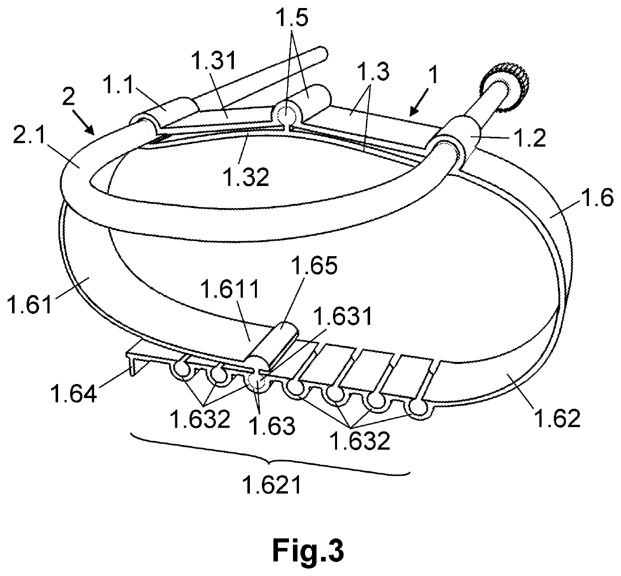
[0028]FIG. 3 represents a perspective view of the device of FIGS. 1 and 2, with a strap for securing it to the user.

third embodiment

[0029]FIG. 4 represents a perspective view of the device of FIGS. 1 and 2, with a strap for securing it to the user.

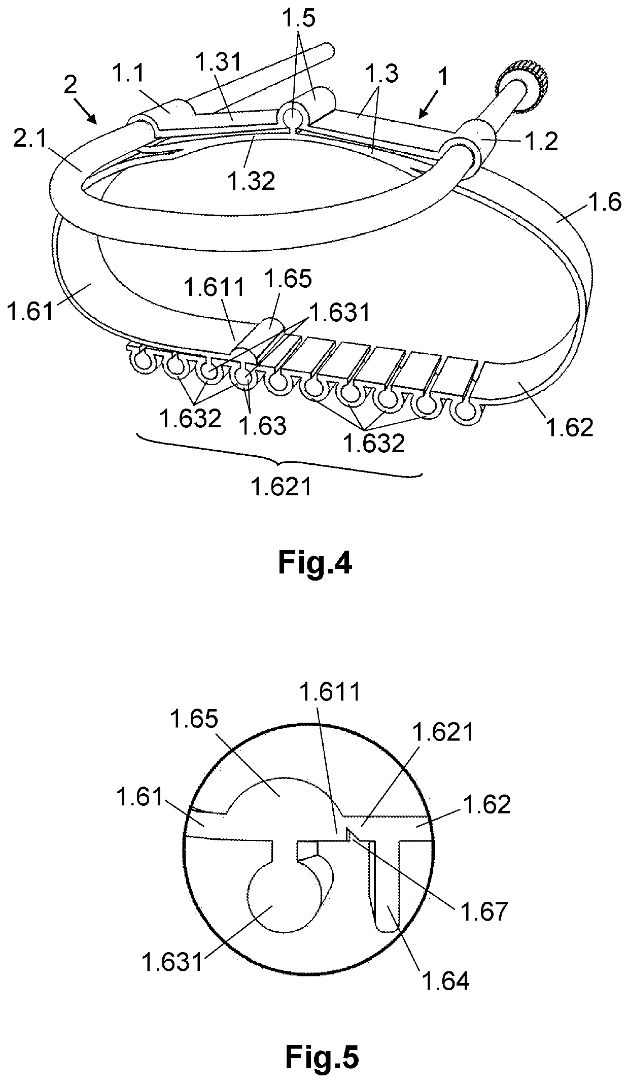
[0030]FIG. 5 represents an enlarged view of the securing strap of the device of any of FIG. 3 or 4, showing how the fastening strap can be closed around the perimeter to facilitate its manufacture, and then can be cut for installation on the user.

[0031]DETAILED EXPLANATION OF THE INVENTION

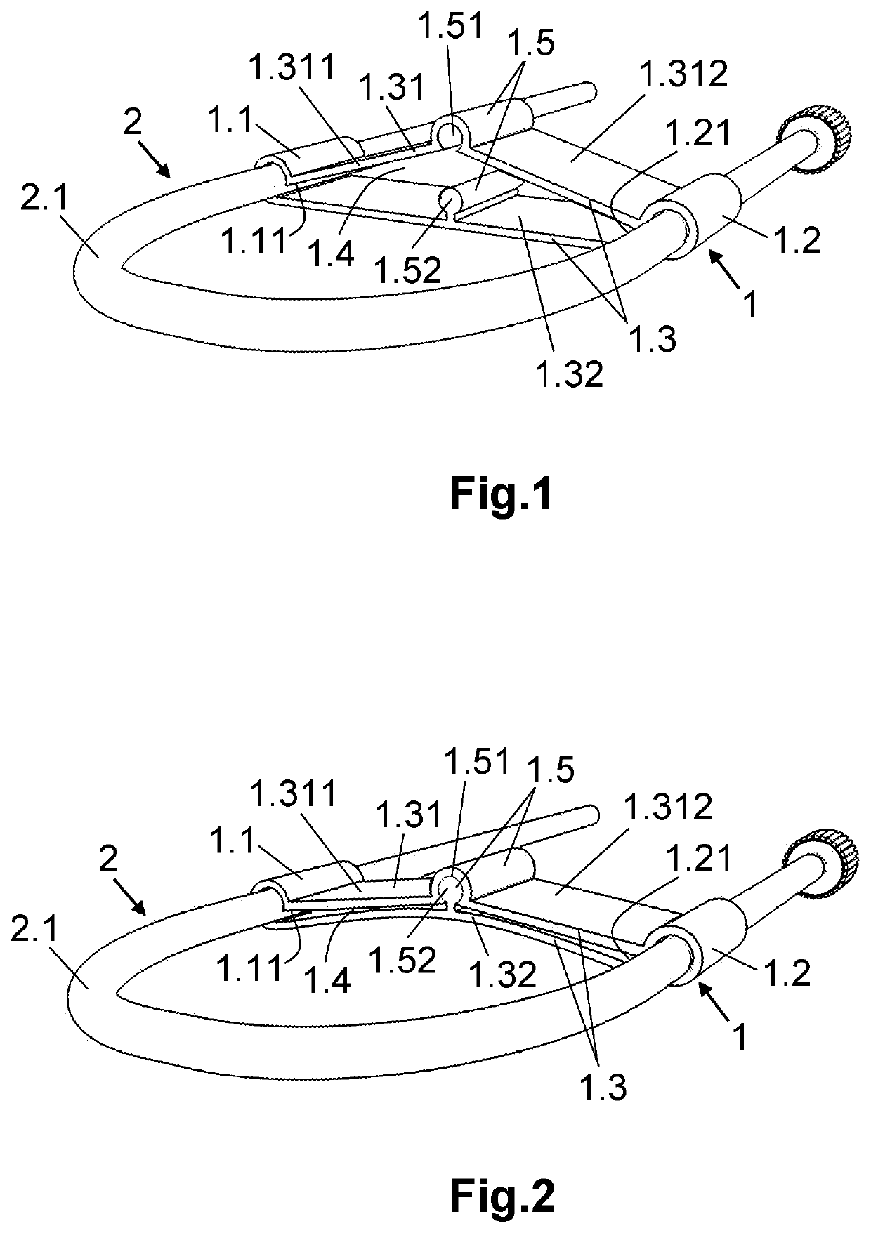
[0032]The present invention is a device for securing a peripheral venous catheter, of the type usually fastened in a curved or folded arrangement, forming a safety loop.

[0033]As shown in FIGS. 1 and 2, the device includes a body (1) comprising:[0034]a first fastening extremity (1.1),[0035]a second fastening extremity (1.2) and[0036]a connecting section (1.3) that interconnects the first fastening extremity (1.1) and the second fastening extremity (1.2).

[0037]Preferably, the body (1) comprises a constant cross section throughout its length and, further, it can advantageously be manufac...


PUM


Abstract

A device for securing a peripheral venous catheter, including a body comprising first and second fastening extremities and a connecting section that interconnects said fastening extremities, the latter feature a tubular shape and comprising corresponding first and second longitudinal grooves; a portion of the catheter may be inserted through said grooves to grasp the same in a folded manner, the connecting section comprises first and second portions extending between the longitudinal grooves, in such a way that the fastening extremities and the portions of the connecting section form a closed perimeter outline defining a hollow internal space adapted to be set between an open position and a closed position, where, the hollow internal space being open, the portion of the catheter may be inserted for the attachment thereof to the fastening extremities, and then secured to the latter when the hollow internal space is closed.

Description

TECHNICAL FIELD OF THE INVENTION[0001]The present invention is encompassed in the field of medical devices, specifically those used to secure peripheral venous catheters, which are usually fastened in a curved or folded arrangement forming a safety loop.BACKGROUND OF THE INVENTION[0002]The health system requires an effective device that guarantees the safety of the peripheral venous catheter, for example, in medical emergencies.[0003]Various devices are known that attempt to ensure the fastening of peripheral venous catheters. For example, patent document US2006047268 shows a catheter retention clamp that includes first and second straight body parts, which extend along respective longitudinal axes parallel to each other. These straight body parts are connected by an extension part extending around a 180° curve, which defines a curve of a catheter that is inserted into a U-shaped channel extending through the first straight part, the connection part and the second straight part, whe...

Claims


Application Information

Patent Timeline
Patent Type & Authority Applications(United States)
IPC IPC(8): A61M25/02
CPCA61M25/02A61M2025/028A61M2025/0253A61M2025/0213A61M2025/024A61M2039/087
Inventor PENALBA CORPAS, MIGUEL ANGEL
Owner STABLE U MEDICAL DEVICES SL
Learn More