Particulate and pressure redirection shield for an electric circuit breaker

a technology of electric circuit breakers and shields, which is applied in the field of shields or barriers for magnetic circuit breakers, can solve the problems of inacceptable fouling of such breaker components, and achieve the effects of facilitating the re-direction of pressurized air, and minimizing or eliminating the potential for gas

Active Publication Date: 2016-08-09
SENSATA TECHNOLOGIES INC
View PDF3 Cites 0 Cited by
  • Summary
  • Abstract
  • Description
  • Claims
  • Application Information

AI Technical Summary

Benefits of technology

[0012]The present invention features a barrier or shield for an electric breaker (e.g., a magnetic electric breaker) as well as an electric breaker including such a barrier. More particularly, such a barrier can suitably protect or effectively block particulate debris from migrating to critical areas of the breaker resulting in the unacceptable fouling of such breaker components (e.g., the trip mechanism). Further, such a barrier can cooperate with other features within the breaker and its enclosure to facilitate the redirection of pressurized air resulting from arc event away from moving parts within the breaker and so it can suitably exit the breaker enclosure. Such a barrier and breaker are particularly suitable for use in telecommunications application such as the circuitry used in connection with data communications. It should be recognized, however, that the barrier and breaker of the present invention is not limited to only telecommunications applications.
[0013]In addition, such barriers or shields are also both easily scaled up or down, and reconfigurable to accommodate different circuit breaker design configurations and current ratings. Such a shield or barrier of the present invention also advantageously significantly decreases the contamination or fouling of a sear pin within the trip mechanism as well as decreasing the overall contamination in the mechanism chamber of a breaker particularly as compared to a breaker that has no such shield.
[0014]In its broadest aspects the present invention features a pressure redirection barrier for an electrical breaker including at least one of a first side segment and a second side segment. In further embodiments such a pressure reduction barrier further include both of the first side segment and a second side segment. As also described herein, such a pressure redirection barrier also can re-direct particulate debris being carried in the pressurized air, thereby reducing the potential for contamination and fouling.

Problems solved by technology

More particularly, such a barrier can suitably protect or effectively block particulate debris from migrating to critical areas of the breaker resulting in the unacceptable fouling of such breaker components (e.g., the trip mechanism).

Method used


Image

  • Particulate and pressure redirection shield for an electric circuit breaker
  • Particulate and pressure redirection shield for an electric circuit breaker
  • Particulate and pressure redirection shield for an electric circuit breaker

Examples


example

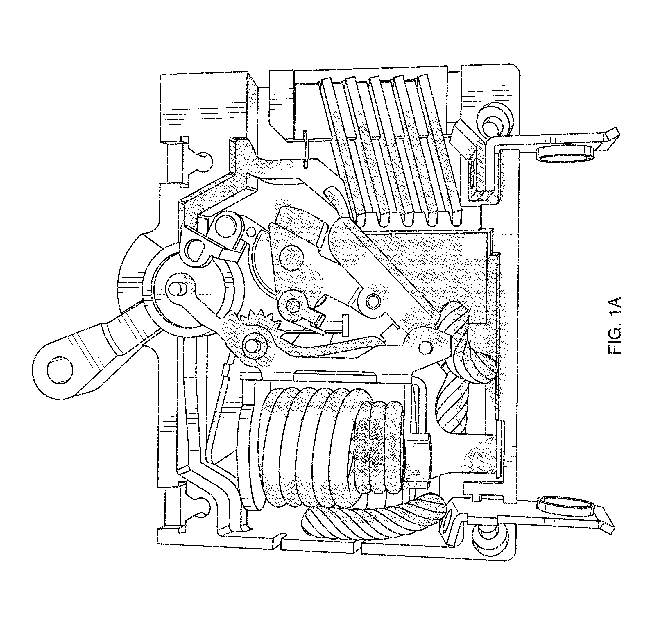
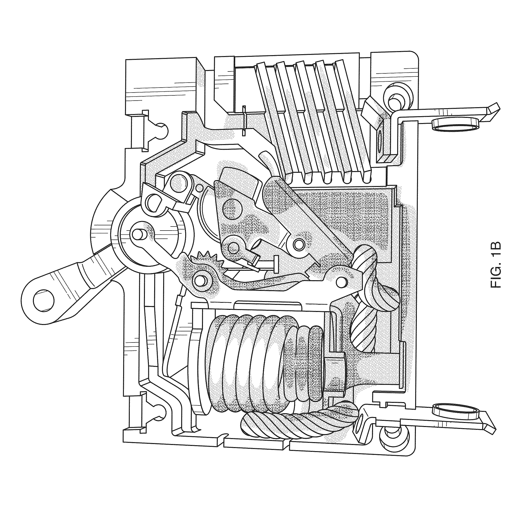
[0098]A test was undertaken to illustrate and show the amount of particulate contamination that might occur with the trip mechanism, the sear pin and the upper armature for a breaker that has no shield and for a breaker including a shield according to the present invention. A pictorial view of a breaker with no shield is provided in FIG. 1. Reference also is made to FIG. 6, which shows a pictorial view of a magnetic breaker configured with a shield according to the present invention.

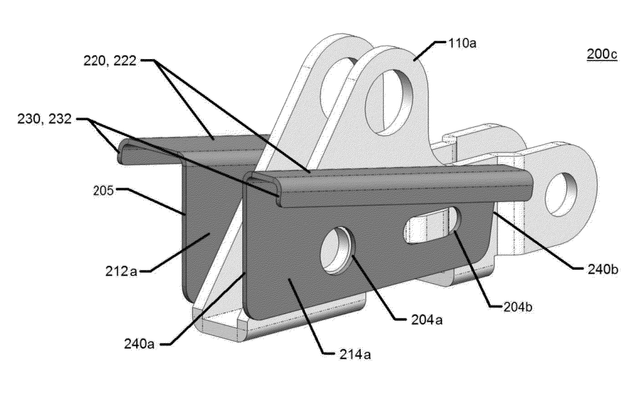
[0099]In this example, the length of the top surface is about 0.508 inches, the width of the second segment is about 0.109 inches, the width of the third segment is about 0.55 inches and the width of both the fourth and fifth segments is about 0.032 inches. It should be noted that manufacturing considerations in some cases dictated the dimensions for the width (e.g., minimum dimension necessary to allow bending of part). Also, the second and third segments are oriented so as to be essentially perpendicul...


PUM


Abstract

Featured is a particulate and pressure redirection barrier for an electrical breaker as well as a breaker embodying such a barrier. Such a barrier includes first through fifth segments, where the first segment includes a first and second side section and a bottom section that are coupled to each other so as to form a generally U shaped structure. The second segment is coupled to the first side section so it extends outwardly at an angle from the first side section. The third segment is coupled to the second side section so as to extend outwardly and at an angle from the second side section. The fourth segment is coupled to the second segment so as to extend outwardly from and at an angle with respect to the second segment. The fifth segment is coupled to the third segment so as to extend outwardly from and at an angle with respect to the third segment. Such a configuration of the fourth and fifth segments is such that gas flowing along a surface of the second or third segments is redirected at an angle with respect to that surface.

Description

FIELD OF INVENTION[0001]The present invention relates to shields or barriers for circuit breakers, more particularly to magnetic circuit breakers and more specifically to shields and barriers used to re-direct particulate debris and air pressure away from a circuit breaker mechanism during an overload event within a circuit breaker.BACKGROUND OF THE INVENTION[0002]A circuit breaker is a manually or automatically operated mechanical switch that is designed to protect an electrical circuit (e.g., a circuit for a telecommunications application such as a data communications circuit) or an electrical component (e.g., motor, computer, etc.) from damage caused by an overload or short circuit (e.g., fault current). The basic function of the breaker is to detect an overload condition and interrupt current flow. Circuit breakers are made in varying sizes, from small devices that protect an individual household appliance up to large switchgear designed to protect high voltage circuits feeding ...

Claims


Application Information

Patent Timeline
Patent Type & Authority Patents(United States)
IPC IPC(8): H01H33/53H01H9/30H01H73/18H01H33/88H01H9/34
CPCH01H9/30H01H73/18H01H33/53H01H2033/888H01H9/342H01H2009/305
Inventor WEBER, SCOTT
Owner SENSATA TECHNOLOGIES INC
Why Eureka
Try Eureka