


Quick Research
Generate reliable direction feasibility study reports for your R&D in just a few steps.

Technical Q&A
Discover and master advanced knowledge NOW. Basics, ideas, possibilities, all at once.

Find Solutions
As an expert in R&D theories, this can generate solutions to your technical problems instantly.

Evaluate Feasibility
Analyze your overall solution with one click, know your potential R&D risks in advance.

Monitor Landscape
Get weekly tech updates, stay abreast of the latest tech innovations and key insights.
Ophthalmic imaging apparatus, method of controlling opthalmic apparatus and storage medium
a technology of opthalmic apparatus and ophthalmic imaging, which is applied in the field of ophthalmic imaging apparatus, can solve the problems of apparatus not performing averaging processing, affecting the tomographic image, and affecting the accuracy of the obtained image,
- Summary
- Abstract
- Description
- Claims
- Application Information
AI Technical Summary
Benefits of technology
Problems solved by technology
Method used
Image

Examples
first embodiment
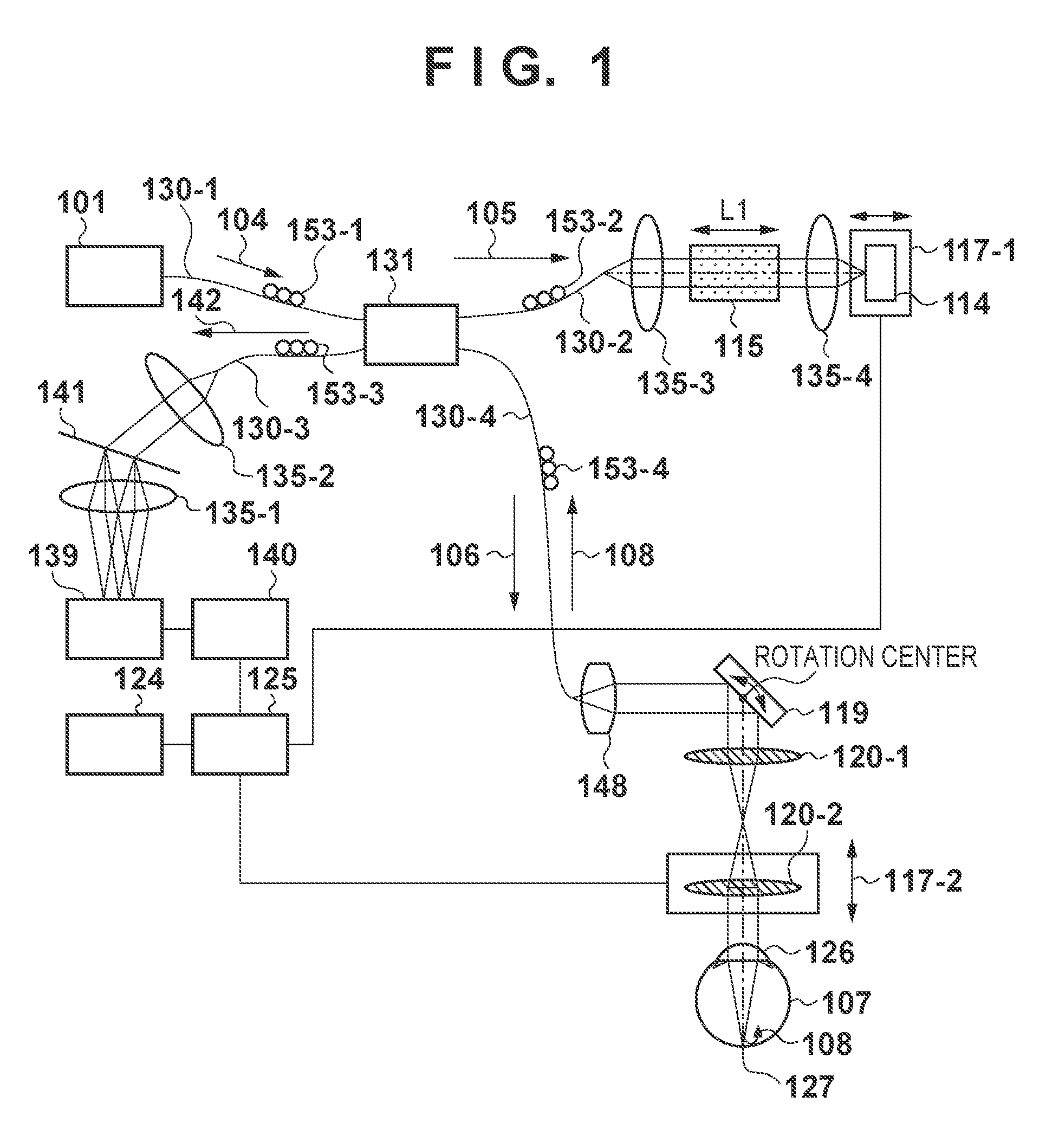
[0023]The first embodiment of the present invention will be described below with reference to FIGS. 1 to 5. FIG. 1 shows the arrangement of an OCT apparatus (ophthalmic imaging apparatus) according to the first embodiment. The OCT apparatus splits light from a light source into measurement light and reference light, and obtains a tomographic image of the eye to be examined based on the wavelength spectrum of interference light between the reference light and return light returning from the eye upon irradiating the eye with the measurement light. Reference numeral 101 denotes a light source; 104, exit light; 105, reference light; 106, measurement light; 142, composite light; 107, an eye to be examined; 108, return light, 130-1 to 130-4, single-mode fibers; 120-1, 120-2, and 135-1 to 135-4, lenses; 114, a mirror; 115, a dispersion-compensating glass; 117, an electrically-driven stage; 119, an XY scanner; 125, a personal computer; 124, a monitor; 126, a cornea; 127, a retina; 131, an o...
second embodiment
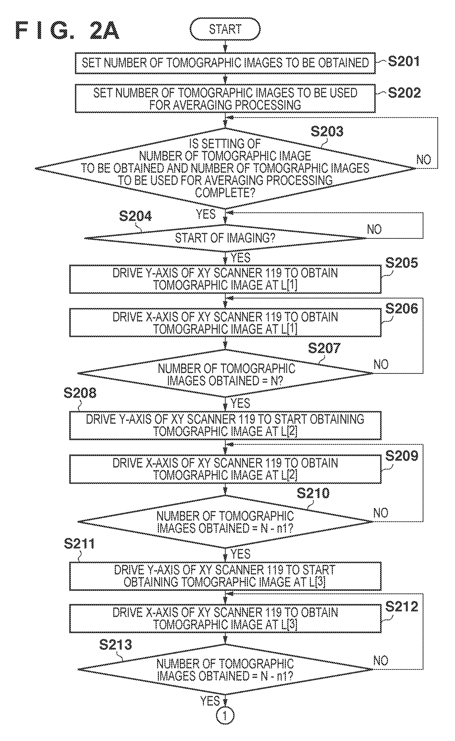
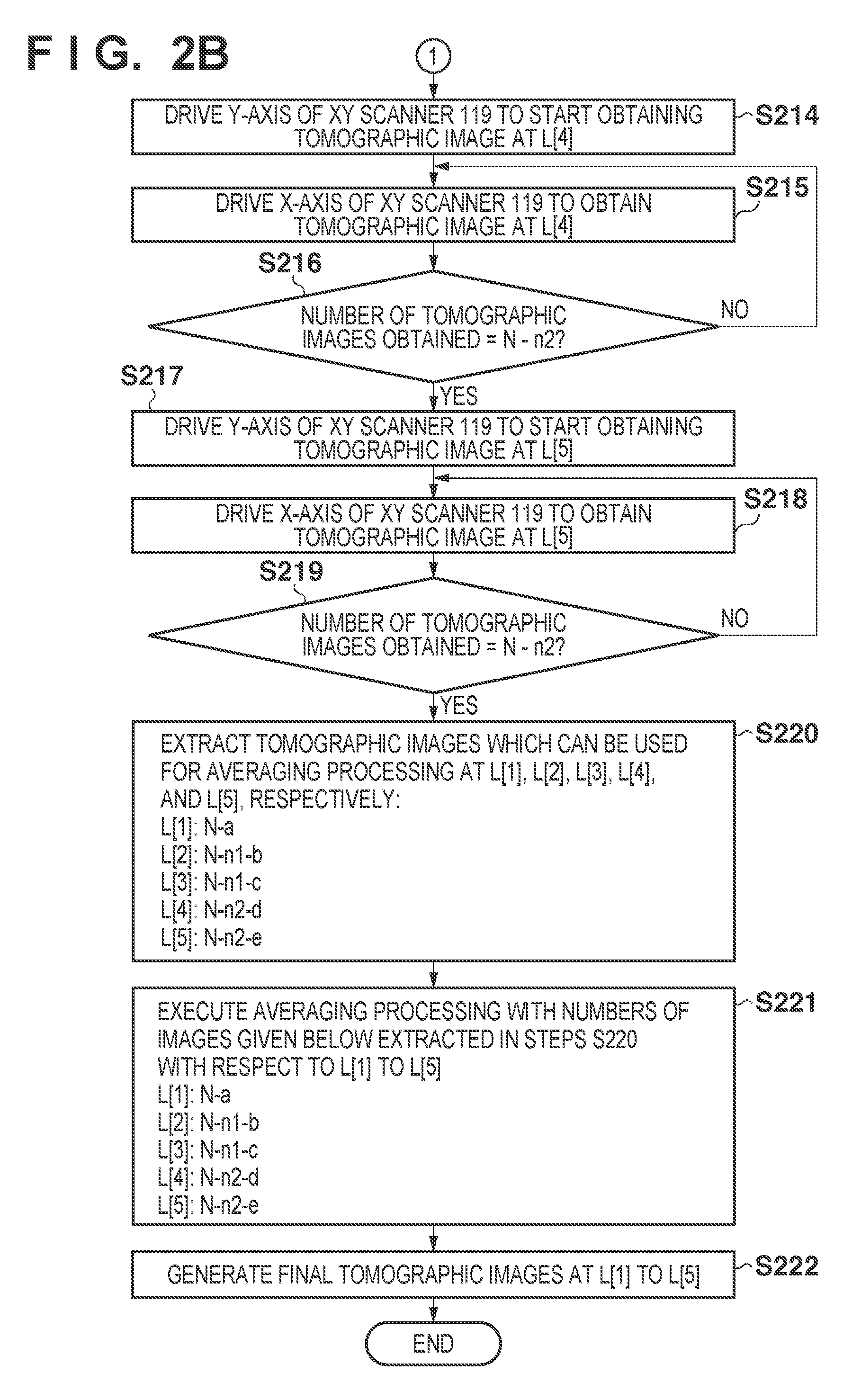
[0070]The second embodiment of the present invention will be described with reference to FIG. 6. The arrangement of an OCT apparatus according to the second embodiment is the same as that of the OCT apparatus shown in FIG. 1 described in the first embodiment, and hence a description of the arrangement will be omitted. FIG. 6 is a flowchart showing the processing operation performed by the CPU of a personal computer 125 according to the second embodiment. The processing in each of steps S201 to S204 described with reference to the flowcharts of FIGS. 2A and 2B is changed to that in each of steps S601 to S621.
[0071]In step S601, the CPU drives an XY scanner 119 in the Y-axis direction to a position to obtain a tomographic image at a scanning region L[1].
[0072]In step S602, the CPU drives the XY scanner 119 in the X-axis direction to obtain a tomographic image at the scanning region L[1] in the X-axis direction (horizontal direction).
[0073]In step S603, the CPU calculates an S / N (Signa...
third embodiment
[0082]The third embodiment of the present invention will be described with reference to FIGS. 7 and 8. FIG. 7 shows the arrangement of an OCT apparatus according to the third embodiment. Note that the same reference numerals as in FIG. 1 denote the same constituent elements in FIG. 7.
[0083]An objective lens 302 is disposed to face an eye 107 to be examined. A perforated mirror 303 provided on the optical axis splits light into an optical path 351 and an optical path 352.
[0084]The optical path 352 forms an illumination optical system which illuminates the fundus of the eye 107. The illumination optical system includes a halogen lamp 316, a strobe tube 314, a lens 309, a lens 311, an optical filter 310, a ring slit 312, a condenser lens 313, a condenser lens 315, and a mirror 317. The halogen lamp 316 is used to position the eye 107. The strobe tube 314 is used to image the fundus of the eye 107. The ring slit 312 forms illumination light from the halogen lamp 316 and the strobe tube ...
PUM
 Abstract
Description
Claims
Application Information
 - R&D Engineer
- R&D Manager
- IP Professional
- Industry Leading Data Capabilities
- Powerful AI technology
- Patent DNA Extraction
Browse by: Latest US Patents, China's latest patents, Technical Efficacy Thesaurus, Application Domain, Technology Topic, Popular Technical Reports.
© 2024 PatSnap. All rights reserved.Legal|Privacy policy|Modern Slavery Act Transparency Statement|Sitemap|About US| Contact US: help@patsnap.com