Ophthalmic apparatus and method for measuring an eye

a technology which is applied in the field of ophthalmic apparatus and eye measurement, can solve the problems of not being able to distinguish between the right or the left eye and the registered eye, the inability to detect infrared light emitted from the examinees' face, and being sensitive to errors caused, so as to achieve the effect of reliable ability to detect which eye is examined

Active Publication Date: 2014-10-02
REVENIO GROUP CORPORATION
View PDF1 Cites 2 Cited by
  • Summary
  • Abstract
  • Description
  • Claims
  • Application Information

AI Technical Summary

Benefits of technology

The described invention solves problems with eye discrimination and automatically detects which eye is being measured. It ensures that the measurement result is linked to the correct eye. This reliable method reduces human errors and speeds up the measurement process. The invention uses two light sources and a detector to detect the reflection of the light beams. By alternating the light sources, the detector can identify which eye the ophthalmic apparatus is aligned to. The invention is immune to interference and has a reliable ability to detect which eye is examined.

Problems solved by technology

The device can, however, not usually distinguish between the right or the left eye and the registered result, thus, does not involve the information about which eye the result is concerned with.
Infrared light emitted from examinees' faces is, however, quite weak to be detected and is not always possible to be discriminated from the environmental light.
Even this system, however, is sensitive for errors caused by interfering infrared light from the environment, such as sunshine.

Method used


Image

  • Ophthalmic apparatus and method for measuring an eye
  • Ophthalmic apparatus and method for measuring an eye
  • Ophthalmic apparatus and method for measuring an eye

Examples


Embodiment Construction

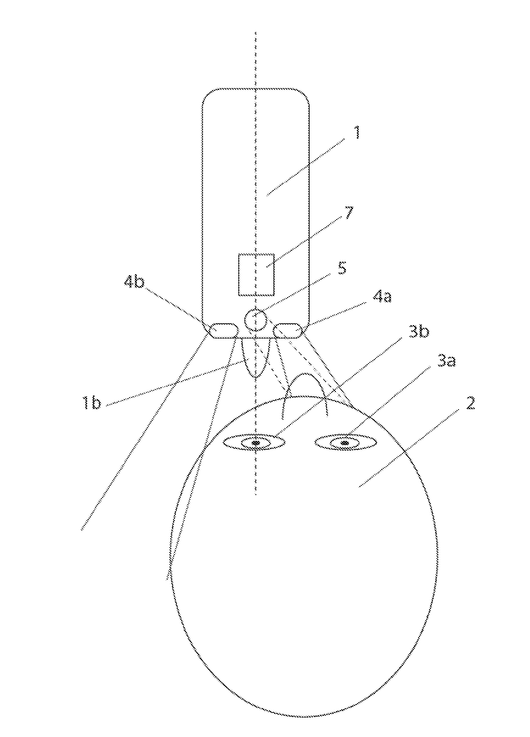
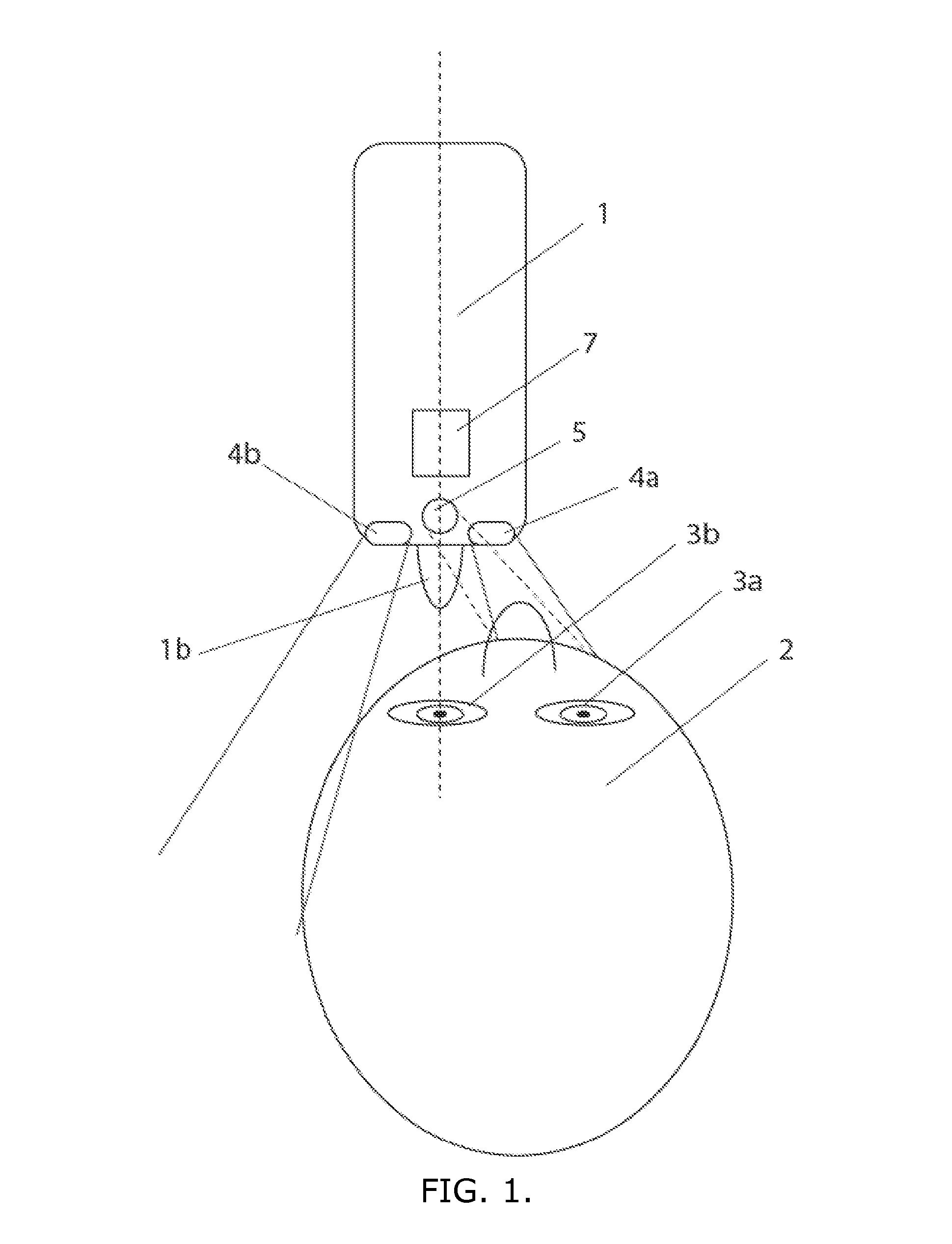
[0041]FIG. 1 is an illustration of an ophthalmic apparatus 1 of the invention, when it is aligned to measure the left eye 3b of an examinee by the examining means 1b of the apparatus.

[0042]The apparatus of FIG. 1 has two infrared light sources 4a, 4b of which one 4a is in FIG. 1 directed to the center of the examinee's face, and the other infrared light source 4b is directed so that the light beam completely passes outside the head 2 of the examinee. The direction of the light beams is indicated with lines in the figure. The light beams of these sources 4a, 4b can e.g. be 90° in relation to each other. Other angles are possible and the optimal angle depends e.g. on the size of the ophthalmic instrument and the distance between the two light infrared sources. There are also means 7 for registering the examination result of the eye and the eye that was examined.

[0043]The detector 5 detects the light that reflects from the examinee's face, which is indicated with dashed lines in FIG. 1...


PUM

PropertyMeasurementUnit
wavelength rangeaaaaaaaaaa
wavelengthsaaaaaaaaaa

Abstract

The ophthalmic apparatus is aligned to an eye to be examined. The apparatus is used to examine the eye. It has two or more infrared or near infrared light sources for emitting light beams and a detector sensitive to infrared or near-infrared light with the capability of detecting the light reflected from the examinee's face. It registers the examination result of the eye examined. The ophthalmic apparatus is aligned to an eye to be examined. The light beam of one infrared or near infrared light source is directed to the face. The light beam of another infrared or near infrared light source is directed to pass the examinee. The direction of the light reflected from the examinee's face is detected and the examination result and the examined eye are registered to know whether the examined eye was the right eye or the left eye

Description

TECHNICAL FIELD[0001]The invention is concerned with an ophthalmic apparatus and a method for measuring an eye.BACKGROUND OF THE INVENTION[0002]An ophthalmic device or apparatus (also called ophthalmologic device or ophthalmometer) is typically aligned to measure one eye, the right or the left eye, of an examinee and the measuring result is registered by the device. The device can, however, not usually distinguish between the right or the left eye and the registered result, thus, does not involve the information about which eye the result is concerned with.[0003]Since ophthalmologic measurement results, such as those of tonometer measurements, and measurements related to the cornea, are different for the right and the left eye, it is important to know whether the measurement result relates to the right or the left eye of the examinee. For the time being there does not exist any ophthalmic device on the market that would be able to give this information reliably and automatically.[00...

Claims


Application Information

Patent Timeline
Patent Type & Authority Applications(United States)
IPC IPC(8): A61B3/10
CPCA61B3/10A61B3/0008A61B3/103A61B3/152
Inventor ERALUOTO, MARKKU
Owner REVENIO GROUP CORPORATION
Why Eureka
Try Eureka