
Map change detection device, map change detection method, and program

a technology of change detection and detection method, applied in the field of map change detection device, can solve the problems of not being able to detect new buildings, failure to match images, and failure to detect originally demolished houses, etc., and achieve the effect of keeping costs down

Inactive Publication Date: 2008-12-04
NEC SOLUTION INNOVATORS LTD
View PDF5 Cites 44 Cited by
  • Summary
  • Abstract
  • Description
  • Claims
  • Application Information

AI Technical Summary

Benefits of technology

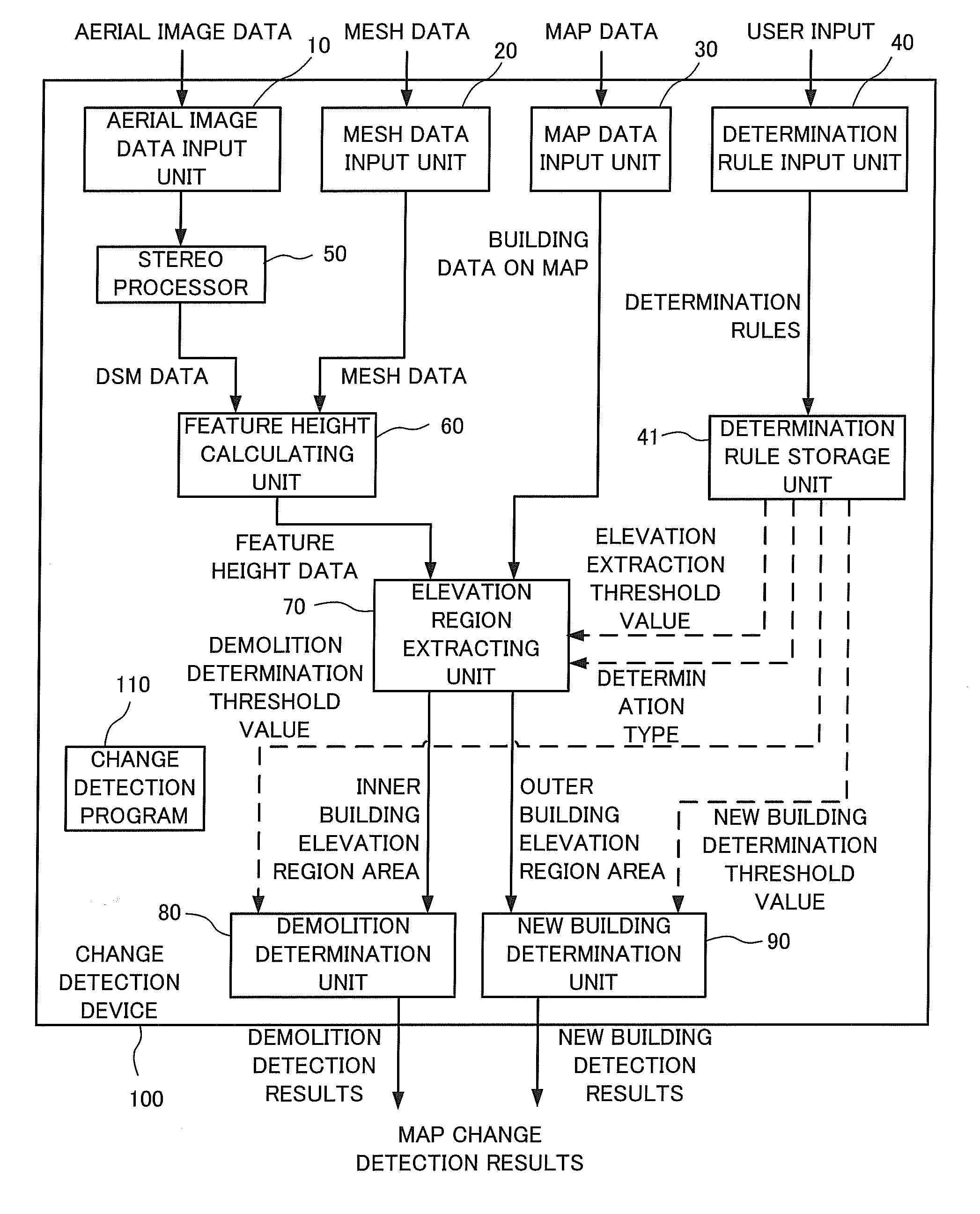
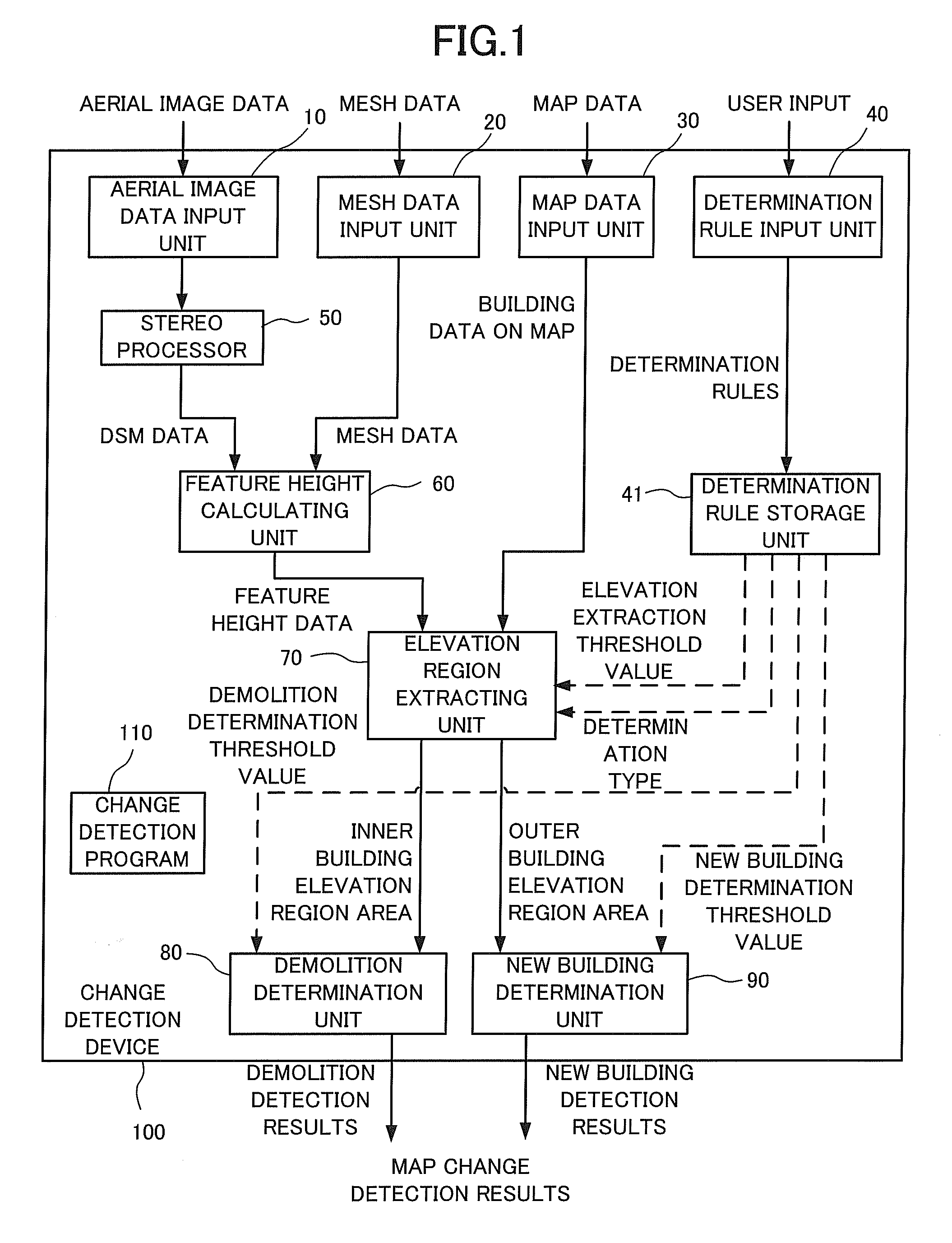
The present invention provides a map change detection device, method, and computer-readable storage medium that can automatically detect changes in buildings on a map and only detect locations of buildings that have changed. This helps to keep down costs involved in detecting changes and reduces detection omissions. The device uses stereo matching processing to extract digital surface model data representing surfaces of predetermined regions in three-dimensional coordinates, feature height extraction to extract feature heights where an elevation from ground level is subtracted, and a change detector to detect change in a feature that is the target by comparing feature height data and map data.

Problems solved by technology

The following problems were, however, encountered with the related technology explained above.
This means that when a large number of similar shaped houses exist, failures occur in the image matching and there are therefore cases where originally demolished houses are not detected.
The problem also exists that new buildings such as when a building that is not on the map is newly built will not be detected because it has been assumed that a building already exists on the map.
This checking is prohibitively expensive and is a manual operation which means that detection omissions may occur.

Method used


Image

  • Map change detection device, map change detection method, and program
  • Map change detection device, map change detection method, and program
  • Map change detection device, map change detection method, and program

Examples


applied example

[0140]An applied example explained in the following is an example of a specific application to a change detection device shown in the embodiment of the present invention. The applied example adopts the same basic configuration and basic operation as the embodiment. The following is mainly a description of points of distinction with the embodiment, with aspects of the configuration and operation that are common to the embodiment being omitted from the description as appropriate.

[0141]A detailed description for a process up to extracting extracted feature height data is given with reference to FIG. 11 to FIG. 15.

[0142]FIG. 11 is a schematic view showing an example of a situation on the ground in the real world. FIG. 11 shows a real world partial cross-section, with features existing on undulating geographical features.

[0143]FIG. 12 is a schematic view showing DSM data generated by stereo matching processing from aerial images taken partially in the real world shown in FIG. 11. The DSM...


PUM


Abstract

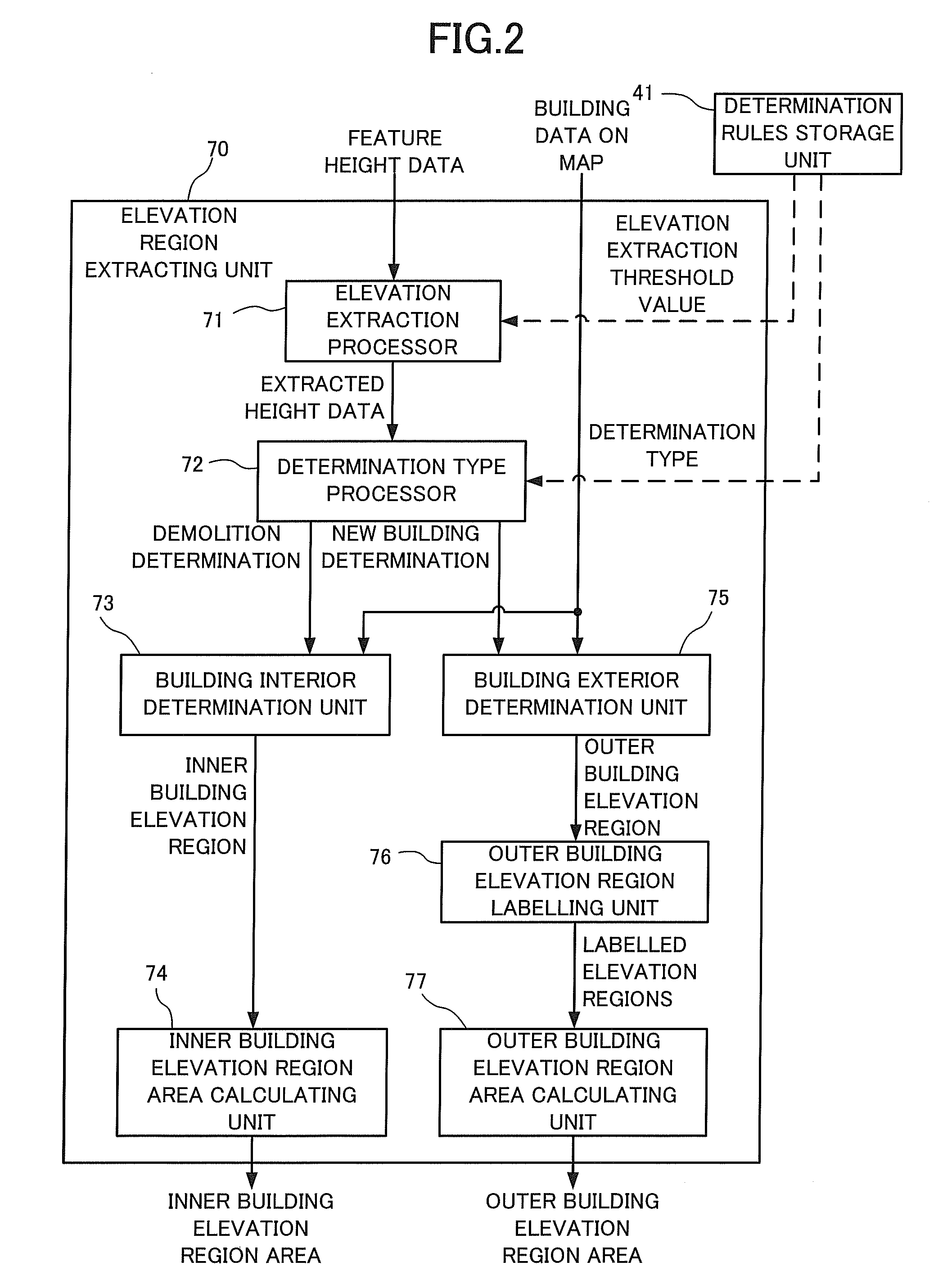
Changes in houses and buildings on a two-dimensional map are detected using three-dimensional data obtained from stereo images. A change detection device that detects changes in features that are targets described on a map has a stereo processor, a feature height calculator, and a demolition and / or new building detector. The stereo processor is inputted with a plurality of images taken of predetermined regions from a plurality of different positions, and extracts digital surface model data representing surfaces of the regions in three-dimensional coordinates. The feature height calculator extracts feature heights where an elevation of ground level is subtracted from the digital surface model data extracted by the stereo processor. The demolition and / or new building detector detect changes in the feature that are the targets described on a map by comparing feature height data and map data. An elevation region extractor extracts an elevation region that is a set of points having a height greater than or equal to the predetermined value, compares the elevation region and the map data, and detects changes in the feature constituting the targets.

Description

[0001]This application is based upon and claims the benefit of priority from Japanese patent application No. 2007-145971, filed May 31, 2007, the disclosure of which is incorporated herein in its entirety by reference.BACKGROUND OF THE INVENTION[0002]1. Field of the Invention[0003]The present invention relates to a map change detection device that detects changes such as changes in houses and buildings on a map. The present invention more specifically relates to a map change detection device, a map change detection method, and a map change detection program that detect changes in houses and buildings etc. on a two-dimensional map using digital surface layer model data obtained from a stereo image.[0004]2. Description of the Related Art[0005]As a method of detecting changes in maps, a method of detecting changes in housing exists where a map is projected onto aerial photographs. Changes in housing are then detected by comparing the buildings on the map and the buildings on the aerial...

Claims


Application Information

Patent Timeline
Patent Type & Authority Applications(United States)
IPC IPC(8): G06K9/00G06T17/05
CPCG06T2207/10032G06T2207/30181G06K9/00637G06K9/00664G06K9/00704G06T7/20G06T2200/04G06T2207/10021G06V20/176G06V20/10G06V20/39
Inventor MIYAZAKI, TOHRU
Owner NEC SOLUTION INNOVATORS LTD
Learn More