
Backrest made of plastic comprising functional elements made of or coated with plastic

a technology of functional elements and backrests, applied in the field of vehicle seats, can solve the problems of relatively heavy and expensive seat materials

Inactive Publication Date: 2015-03-24
SITECH SITZTECHNIK GMBH
View PDF27 Cites 4 Cited by
  • Summary
  • Abstract
  • Description
  • Claims
  • Application Information

AI Technical Summary

Benefits of technology

[0010]It is therefore an object of invention to provide a seat structure, particularly a backrest for a front seat, in which instead of the metal structure used thus far a high proportion of the structure is formed of a plastic. In this regard, the manufacture of such a product is simple, rapid, and cost-effective.
[0013]The reinforcing stiffening element is advantageous because the functional elements disposed between the beams of the backrest also transmit forces to the beams in case of a crash and with a normal load. These forces can be absorbed better by a frame-reinforcing stiffening element disposed in the frame.
[0015]The advantage of the use of a fiber-reinforced plastic is its properties. Fiber-reinforced plastic has a high weight-based strength and rigidity, as well as a high vibration damping capacity and a high fatigue limit. Moreover, other properties are a low thermal expansion and a very good UV resistance. In addition, fiber-reinforced plastic has a very good formability and thus can be made into virtually any shape, whereby, in addition, simultaneously a color preselection for the components to be manufactured is possible with the use of colored fibers. Fiber-reinforced plastic can be used very well in the aforementioned and briefly described injection molding process.

Problems solved by technology

Seats made of metal constructions are relatively heavy and expensive.

Method used


Image

  • Backrest made of plastic comprising functional elements made of or coated with plastic
  • Backrest made of plastic comprising functional elements made of or coated with plastic
  • Backrest made of plastic comprising functional elements made of or coated with plastic

Examples


first embodiment

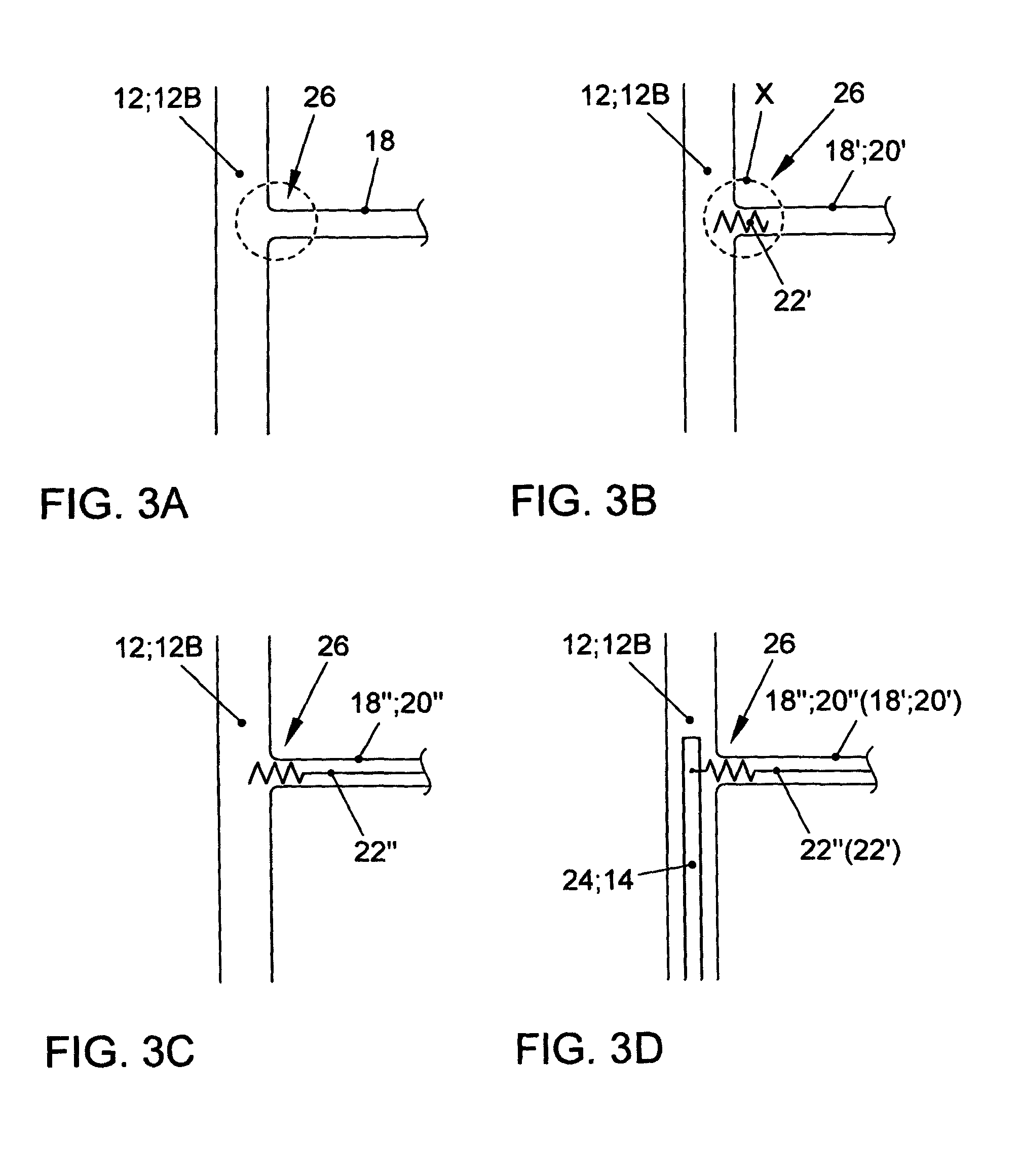
[0044]The first embodiment variant is used to replace the known wire mat in the back area of a seat user.

[0045]First embodiment of the first embodiment variant:

[0046]Plastic bar 18 between beams 12B of backrest 10 (without inserts).

second embodiment

[0047 of the first embodiment variant:

[0048]Plastic bar 18′ between beams 12B of backrest 10 with a partial insert 22′.

third embodiment

[0049 of the first embodiment variant:

[0050]Plastic bar 18″ between beams 12B of backrest 10 with a complete insert 22″.

[0051]The second embodiment variant is used to replace the known lumbar support in the lumbar area of a seat user.

[0052]First embodiment of the second embodiment variant:

[0053]Plastic plate 20 between beams 12B of backrest 10 (without inserts).

[0054]Second embodiment of the second embodiment variant:

[0055]Plastic plate 20′ between beams 12B of backrest 10 with a partial insert 22′.

[0056]Third embodiment of the second embodiment variant:

[0057]Plastic plate 20″ between beams 12B of backrest 10 with a complete insert 22″.

[0058]In the first embodiment of the first embodiment variant, it is provided to replace the wire mat by at least one plastic bar 18 disposed between beams 12B of backrest 10.

[0059]The term plastic bar 18 does not mean that it refers only to a straight, bar- like plastic element between beams 12B of the backrest. Plastic bar 18 can be formed in the sh...


PUM

PropertyMeasurementUnit
areaaaaaaaaaaa
resilientaaaaaaaaaa
modulus of elasticityaaaaaaaaaa

Abstract

A backrest is provided, whereby a frame-shaped base structure of which is made of a dimensionally stable plastic, The base structure being formed from beams. The frame-shaped base structure includes at least one functional element between the beams, and the at least one functional element is made only of a plastic and / or as a plastic-coated insert. Injection molding is proposed as a production method.

Description

[0001]This nonprovisional application is a continuation of International Application No. PCT / EP2011 / 000377, which was filed on Jan. 28, 2011, and which claims priority to German Patent Application No. DE 10 2010 007 052.1, which was filed in Germany on Feb. 6, 2010, and which are both herein incorporated by reference.BACKGROUND OF THE INVENTION[0002]1. Field of the Invention[0003]The invention relates to a vehicle seat with an inherently stable backrest formed of plastic.[0004]2. Description of the Background Art[0005]Seat structures in vehicles are required to meet specific safety standards. These safety standards are higher for front seats in motor vehicles than for their back seats, because the front seats must absorb in addition the impact of the body and head of the back seat passengers. Therefore, most front seat backs are metal constructions, although other materials, particularly plastics or plastic composites with a high modulus of elasticity (high rigidity), can also be us...

Claims


Application Information

Patent Timeline
Patent Type & Authority Patents(United States)
IPC IPC(8): B60N2/42B60N2/66B60N2/68
CPCB60N2/686B60N2/66B60N2/682
Inventor BAUMGARTEN, JENS
Owner SITECH SITZTECHNIK GMBH
Learn More