Robot system controlling method, robot system, and control apparatus for quadrupedal robot
a robot and robot technology, applied in the direction of programmed control, manipulators, instruments, etc., can solve the problems of large amount of computation required in order to generate inputs, time is required for calculations, and the controllability of artificial muscle actuators is known
- Summary
- Abstract
- Description
- Claims
- Application Information
AI Technical Summary
Benefits of technology
Problems solved by technology
Method used
Image
Examples
first embodiment
[0079][First Embodiment]
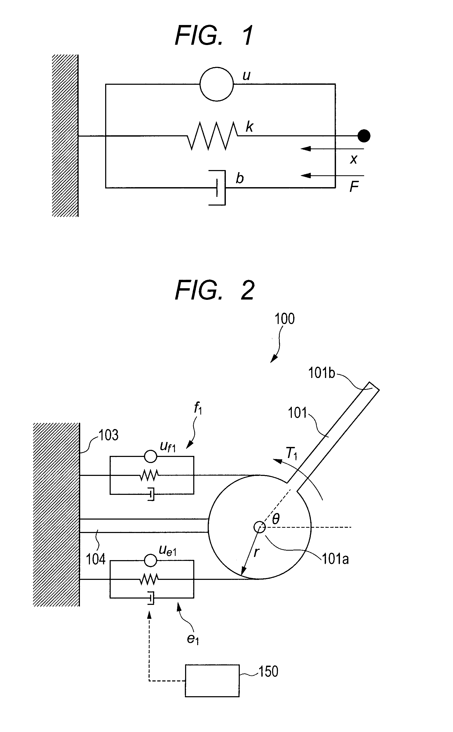
[0080]FIG. 1 is a diagram illustrating a viscoelastic model of an actuator applied to a robot system according to a first embodiment of the present invention. In the first embodiment, a manipulator which uses pneumatic artificial muscle actuators will be taken as an example of the robot system and simultaneous control of a joint angle and stiffness of the manipulator will be described.
[0081](1) Modeling
[0082]An artificial muscle actuator has a property similar to a property called muscular viscoelasticity. As illustrated in FIG. 1, the artificial muscle actuator is modeled using a force generating element, elasticity element, and viscosity element. Let u denote a contraction force of the force generating element and let x denote an amount of contraction of a muscle when a contraction direction is taken as a positive direction, then a contraction speed is given by the following equation.
{dot over (x)}
[0083]Also, let k denote an elastic force constant, let b de...
second embodiment
[0144][Second Embodiment]
[0145]Next, a robot system according to a second embodiment of the present invention will be described in detail. FIG. 7 is an explanatory diagram illustrating a schematic configuration of the robot system according to the second embodiment of the present invention. In this second embodiment, hand stiffness control of a robot system will be described taking as an example a two-link manipulator equipped with three pairs of muscles for a total of six muscles based on artificial muscle actuators.
[0146](1) Modeling
[0147]The robot system according to the present embodiment, i.e., the two-link, three-pair six-muscle manipulator is illustrated in FIG. 7. The robot system 200 includes a first link 201, a second link 202, and a pulley 203 serving as a fixing member.
[0148]The first link 201 is a longitudinal member. A base end 201a of the first link 201 is swingably supported by the pulley 203 within a plane (hereinafter referred to as a “working plane”) of an x-y ort...
third embodiment
[0229][Third Embodiment]
[0230]Next, a robot system according to a third embodiment of the present invention will be described. FIG. 14 is a block diagram illustrating a control apparatus for the robot system according to the third embodiment of the present invention. In this third embodiment, the same components as those in the second embodiment are denoted by the same reference numerals as the corresponding components in the second embodiment, and description thereof will be omitted.
[0231]The second embodiment described above realizes hand stiffness control using the elasticity of muscles as follows: after the joint reaches the target angles, the coefficient values Gt1 and Gt2 which represent contact gain are set to 0, causing the feedback control system to be shut off. However the second embodiment is not designed to give flexibility to the links while following the target trajectory. Also, the axes of the stiffness ellipse are controlled to be parallel to the x and y axes only at...
PUM
 Abstract
Description
Claims
Application Information
 - R&D
- Intellectual Property
- Life Sciences
- Materials
- Tech Scout
- Unparalleled Data Quality
- Higher Quality Content
- 60% Fewer Hallucinations
Browse by: Latest US Patents, China's latest patents, Technical Efficacy Thesaurus, Application Domain, Technology Topic, Popular Technical Reports.
© 2025 PatSnap. All rights reserved.Legal|Privacy policy|Modern Slavery Act Transparency Statement|Sitemap|About US| Contact US: help@patsnap.com


