Support and positioning structure, semiconductor equipment system and method for positioning

a positioning structure and positioning technology, applied in the field of semiconductor equipment systems, can solve the problems of increased risk of mistakes when transferring patterns, inability to include, and inability to operate in vacuum or near vacuum environments

Active Publication Date: 2015-02-10
ASML NETHERLANDS BV
View PDF45 Cites 2 Cited by
  • Summary
  • Abstract
  • Description
  • Claims
  • Application Information

AI Technical Summary

Benefits of technology

[0011]It is therefore an object to provide a semiconductor equipment system with a positioning and support structure that can be positioned in vacuum and nevertheless allows sufficient shielding of its actuators.
[0013]The invention thus creates a shield composed of a first and a second shield part. These shield parts are mutually fitted with an amount of play sufficient in order to enable an appropriate positioning. Still, the first and second shield part together allow for sufficient shielding of the motors.
[0015]Most suitably, the side portions demonstrate mutual overlap. It has been found that such overlap of the side portions dramatically improves the overall performance of the shield, even though the elements to be shielded are on top of the motors instead of aside thereof. A preferred measure of overlap is expressed as the ratio between the distance between such side portions and the length of overlap. This length is defined in the z-direction, which is the direction normal to the exposed surface of the second member. Suitably, the length of overlap is at least fivefold the distance between the side portions. More suitably, the ratio is even 8, 10 or larger than 10.
[0020]An advantageous effect of constructing the support structure in this manner using an interdigitated shielding arrangement is the high ease of assembly and dis-assembly. The interdigitated shielding arrangement not only enables relative movement between but also allows the first and second shield part to be placed or separated without mechanically disturbing the shield parts.
[0021]In a further embodiment, wherein the support and positioning structure is provided with a non-operative state in addition to an operative state, in which non-operative state the at least one motor is turned off and the first and the second member are at mutually increased distance without effecting a leakage in the shield. When putting said motors off or at low power, a stable position is to be ensured for the first member. In this embodiment, the stable position is a position, in which the first and second members are at mutually increased distance. Particularly, the distance is increased or decreased along the z-direction, i.e. the direction parallel to any side portions of the shield parts. The increase in mutual distance is limited so as not to make a leak in the shield.
[0023]In another embodiment, the support and positioning structure is provided with a first and an adjacent second side face that mutually include an oblique angle, e.g. an angle between 90 and 180 degrees. It turns out that such a polygonal shape of the support and positioning structure maximizes freedom of movement in any of the six degrees of freedom.

Problems solved by technology

It is a disadvantage of the known system that the vacuum environment is localized and does not include the positioning and support structure.
The positioning of actual target surface outside the vacuum environment strongly increases the risk of mistakes when transferring a pattern to the target surface.
It is a disadvantage of this known system that radiation cooling does not function adequate in vacuum or near-vacuum environments.
Moreover, the use of a Peltier element in addition to radiation cooling complicates the equipment system.

Method used


Image

  • Support and positioning structure, semiconductor equipment system and method for positioning
  • Support and positioning structure, semiconductor equipment system and method for positioning
  • Support and positioning structure, semiconductor equipment system and method for positioning

Examples


Embodiment Construction

[0038]In the figures, identical reference numbers relate to identical or at least comparable technical features. The Figures are not drawn to scale and intended for illustrative purposes only. The Figures show examples, which are not intended to limit the claims anyhow.

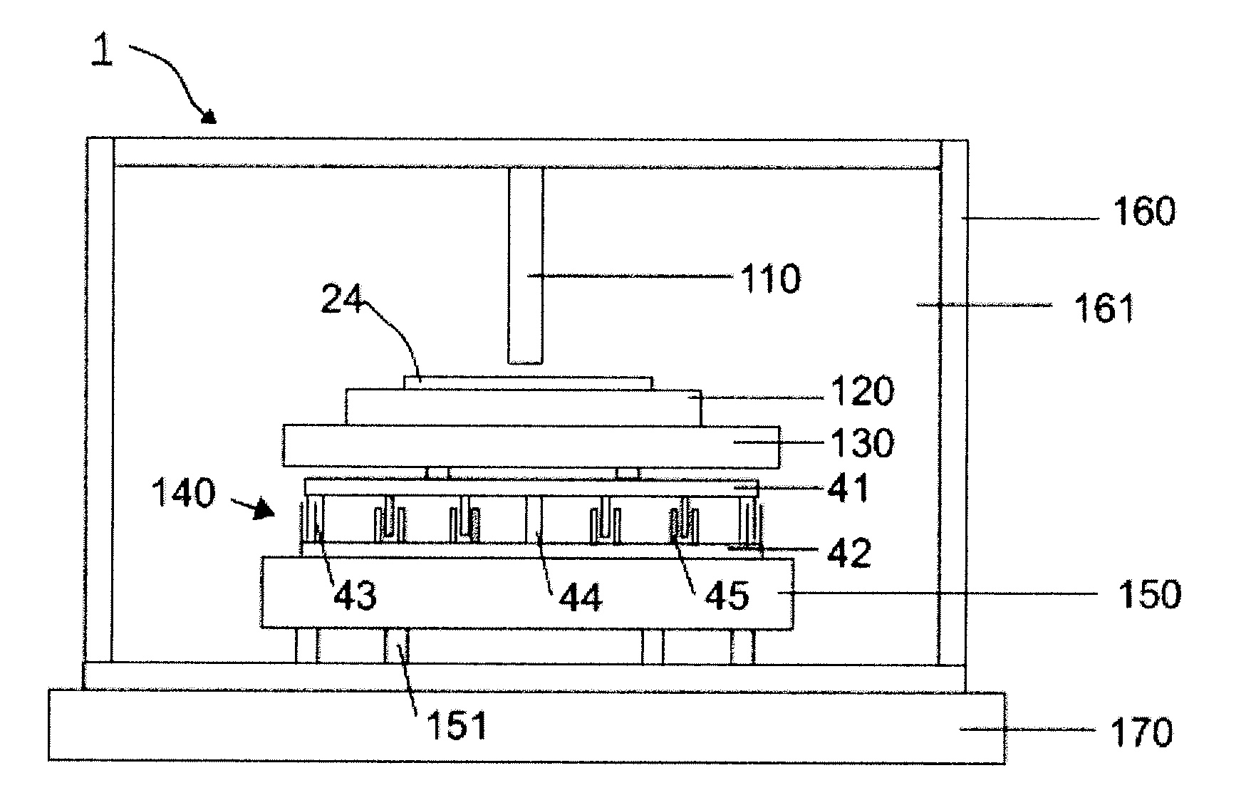
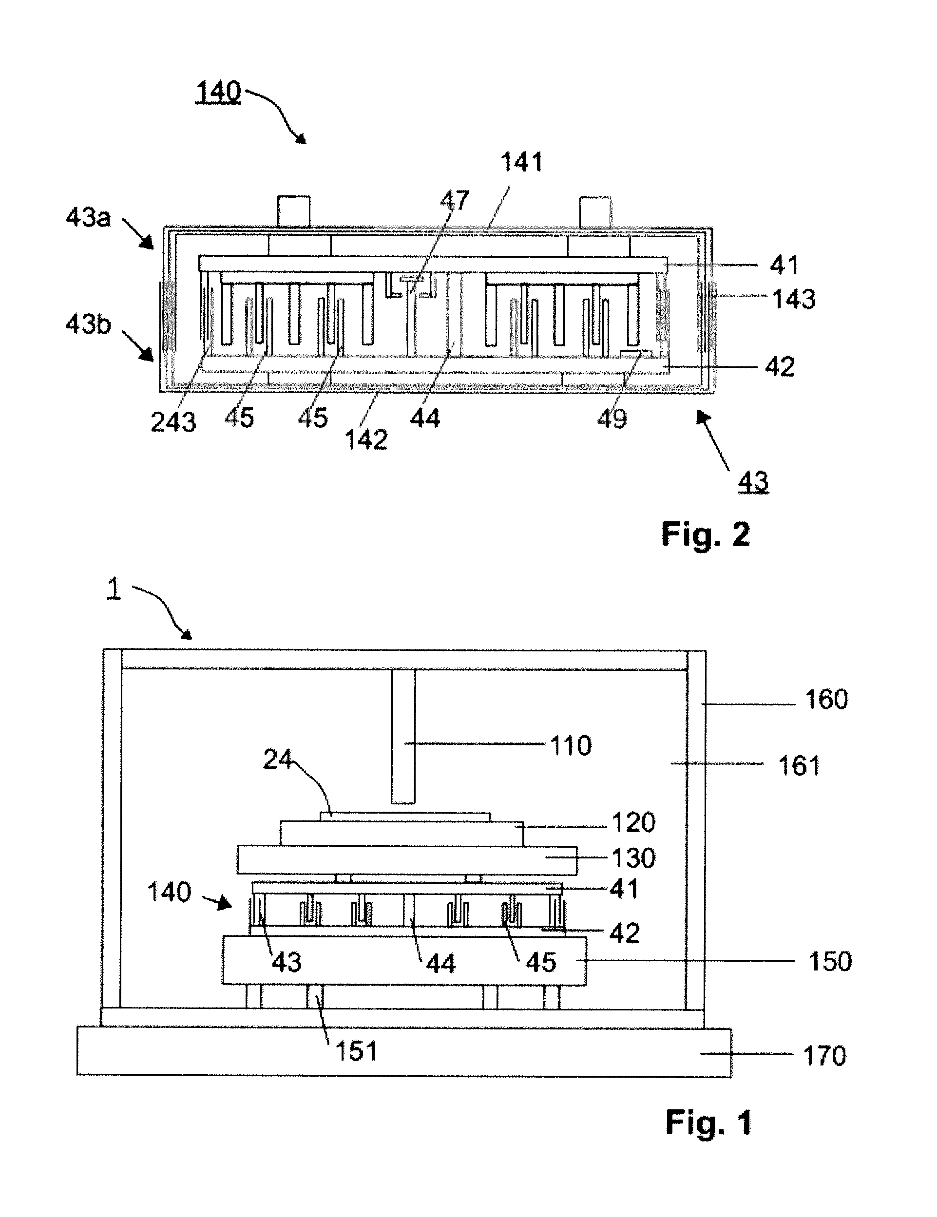
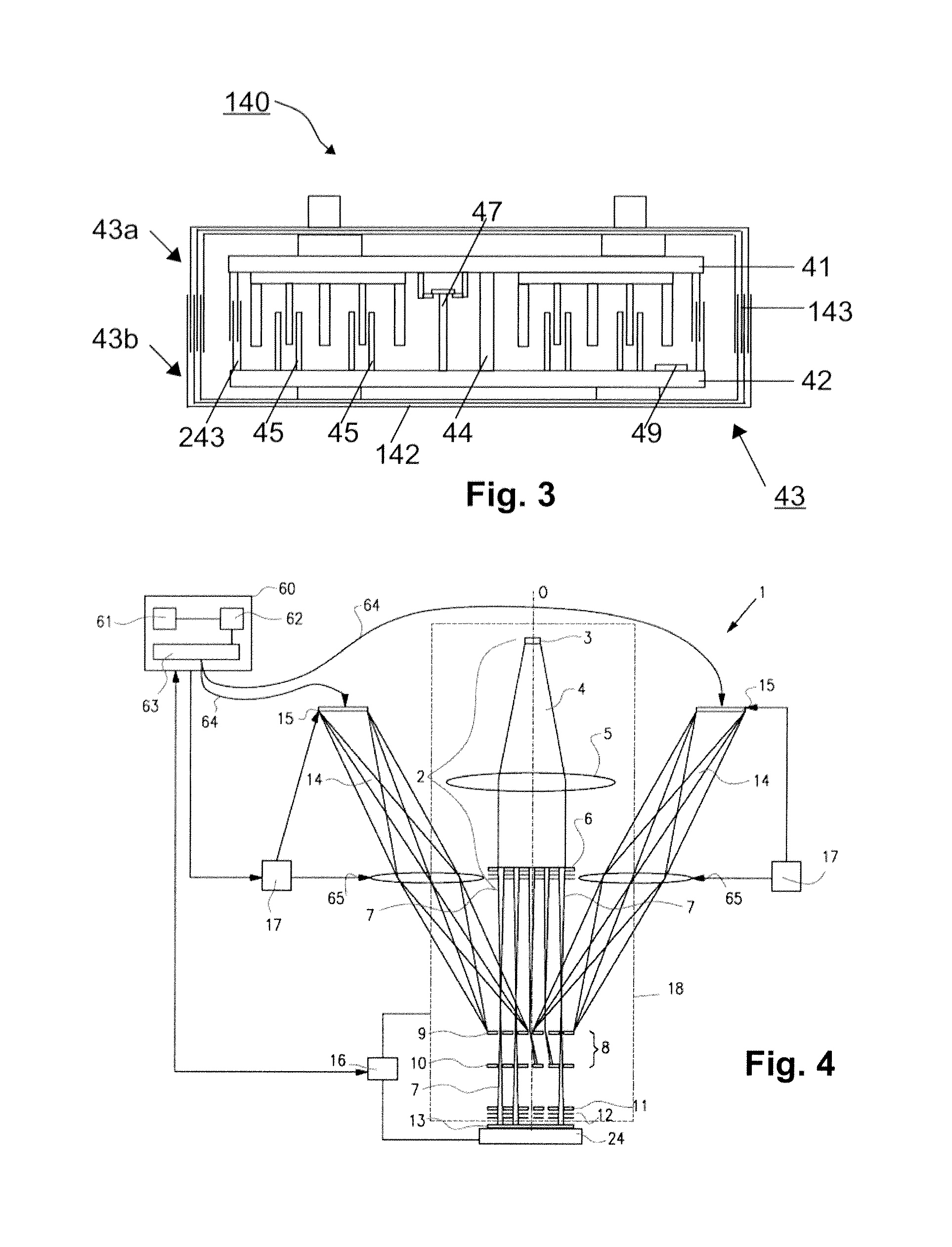
[0039]FIG. 1 shows a schematic cross-sectional view of the semiconductor equipment system 1 according to the invention. The equipment system 1 shown in the present figure is a system with a column 110, and more particularly a lithographic system or an inspection system. Specifically, it is a system in which charged particles beamlets are transmitted to the surface of a target 24. This target 24 is for instance a semiconductor wafer or a mask, though other targets such as an assembly carrier are not excluded.

[0040]In operation, the column 110 transmits beamlets to the target 24. In the case of a lithographic system, the beamlets are transmitted so as to transfer a pattern to at least a major portion of the surface of t...


PUM


Abstract

The invention relates to a charged particle system provided with a support and positioning structure for supporting and positioning a target on a table, the support and positioning structure comprising a first member and a second member and at least one motor so as to move the first member relative to the second member, wherein a shield is present to shield at least one charged particle beam from electromagnetic fields generated by said at least one motor, the support and positioning structure further comprising a spring mechanically coupling the first member and the second member for at least partially bearing the weight of the first member, table and target.

Description

[0001]This is a non-provisional application claiming the benefit of U.S. Provisional Application No. 61 / 287,657 filed Dec. 17, 2009, and U.S. Provisional Application No. 61 / 287,661 filed Dec. 17, 2009.BACKGROUND OF THE INVENTION[0002]1. Field of the Invention[0003]The invention relates to a semiconductor equipment system provided with a support and positioning structure that comprises a first member and a second member and at least one motor.[0004]The invention further relates to such support and positioning structure and to the use thereof.[0005]2. Description of the Related Art[0006]Support and positioning structures are widely used in semiconductor equipment systems, such as lithographic systems and inspection systems. In the case of a lithographic system, the first member is for instance a wafer stage onto which a semiconductor wafer may be attached. A typical example of a measurement system is an electron microscope. In order to achieve high resolutions as under development for...

Claims


Application Information

Patent Timeline
Patent Type & Authority Patents(United States)
IPC IPC(8): H01J37/20
CPCH01J37/20B82Y10/00B82Y40/00H01J37/09H01J37/3177H01J2237/0264H01J2237/202G03F7/70808H01J37/3007H01J37/3056
Inventor PEIJSTER, JERRYMEHENDALE, ADITYAHILDERINK, ANDRE JOHANNES MARIA
Owner ASML NETHERLANDS BV
Why Eureka
Try Eureka