
Device for filling at least one dosing chamber

a technology for dosing chambers and devices, applied in the direction of packaging goods, liquid handling, manufacturing tools, etc., can solve the problems of limited stuffing force generation, unnecessarily generating friction and wear,

Inactive Publication Date: 2015-02-10
ROBERT BOSCH GMBH
View PDF13 Cites 8 Cited by
  • Summary
  • Abstract
  • Description
  • Claims
  • Application Information

AI Technical Summary

Benefits of technology

[0007]The device according to the invention for filling at least one dosing chamber has the advantage over the prior art that because of the synchronous motion of the at least two columns, twisting of the arrangement that carries the rams is avoided. As a result, the wear caused by friction can be minimized as well. In addition, only a single drive has to be provided for the entire arrangement, and as a result the complexity of the system is reduced, and easy regulation is attained.
[0010]The drive is now triggered according to the invention such that the crank mechanism does not execute a complete revolution but instead is merely moved up and down by means of a purposeful reciprocating motion of the drive. The angle by which the crank mechanism is moved from the left reversal position to the right reversal position and vice versa defines the length of the stroke of the support and hence of the ram. By varying the this angle or the location of the reversal points that define this angle, the stroke of the ram can be varied in a very simple way, without requiring a complicated adjustment of the mechanics. In particular, in the variation of the maximum possible stroke, the ram can be moved into a maintenance position in which the dosing disk can easily be cleaned, for instance, without colliding with the rams. Moreover, by means of a skilled selection of the speed and / or acceleration of the drive in the vicinity of the reversal points, the arrangement allows a targeted variation of the stuffing forces. In electric drives, accelerations can easily be defined and modified as a function of position in the controller. With high acceleration, high stuffing forces, and correspondingly with low acceleration, lesser stuffing forces, are attainable.
[0011]In an expedient refinement, it is provided that for each column, its own crank mechanism is provided. To improve the stability of the dosing device, at least three columns are as a rule suitable, all of which are moved up and down synchronously with the same stroke or motion profile by means of only one drive. These crank mechanisms are connected to one another or only to the drive by coupling mechanisms, so that the motion profile predetermined by the drive is available in the same way for the other crank mechanisms as well. The synchronicity of the motion of the columns can thus be assured.

Problems solved by technology

However, only limited stuffing forces can be generated.
Furthermore, it is problematic that with as a rule a separate drive of the columns, the stuffing device twists, which unnecessarily produces friction and wear.

Method used


Image

  • Device for filling at least one dosing chamber
  • Device for filling at least one dosing chamber
  • Device for filling at least one dosing chamber

Examples


Embodiment Construction

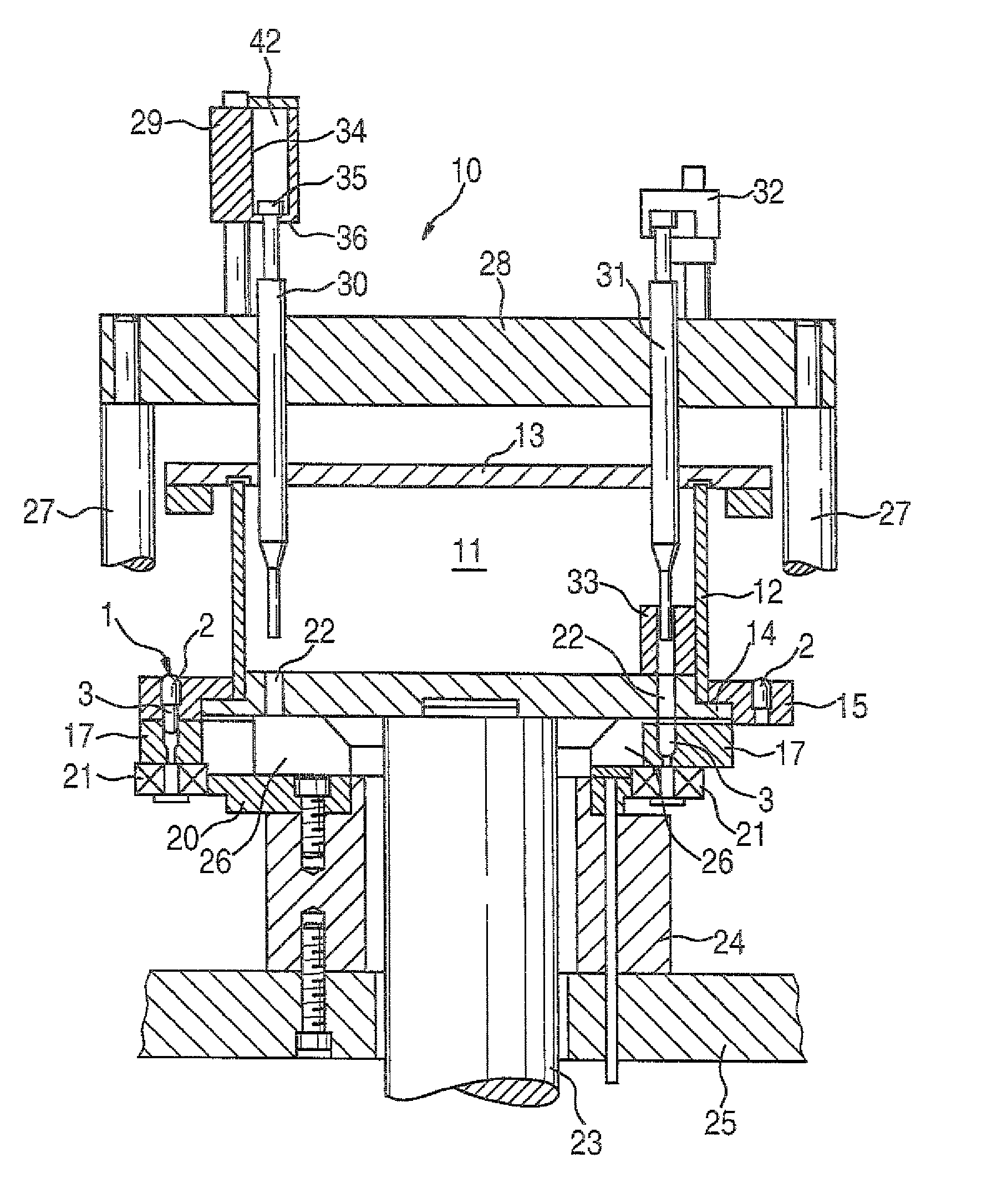
[0018]The device shown in FIG. 1 for filling at least one dosing chamber and then dispensing powder into hard gelatin capsules 1 or the like has a container 11 for material to be dispensed. The container 11 for material to be dispensed is formed by a casing 12, a cap 13, and a dosing disk 14. At the level of the dosing disk 14, the container 11 for material to be dispensed is enclosed by a ring 15 that serves to receive upper capsule parts 2. Below the ring 15, segments 17 are provided, which are correspondingly embodied for receiving lower capsule parts 3. The segments 17 are each pivotably supported by a respective bolt, not shown, that is secured in the ring 15. The segments 17 are attached to a cam roller 21 in a manner such that the segments 17 are moved upon revolution of the dosing disk by engagement of the cam roller 21 with a fixed cam 20 moving cam roller 21 inward, to suit the requirements, or in other words beneath bores or dosing chambers 22 of the dosing disk 14, or ou...


PUM

PropertyMeasurementUnit
accelerationaaaaaaaaaa
stuffing forcesaaaaaaaaaa
lengthaaaaaaaaaa

Abstract

A device for filling at least one dosing chamber is provided, with at least one dosing chamber arranged in a dosing disc into which a filling material is to be introduced. At least one ram acts on the material located in the dosing chamber. The at least one ram is arranged on a support, and at least two columns are connected to the support. A drive mechanism is provided which, via a coupling mechanism, moves at least the two columns up and down in synch.

Description

CROSS-REFERENCE TO RELATED APPLICATION[0001]This application is a 35 USC 371 application of PCT / EP 2007 / 051605 filed on Feb. 20, 2007.BACKGROUND OF THE INVENTION[0002]1. Field of the Invention[0003]The invention is based on a device for filling at least one dosing chamber.[0004]2. Description of the Prior Art[0005]From German Patent DE 100 01 068 C1, a device of this kind for dosing and feeding powder into hard gelatin capsules or the like is already known. This device has an incrementally rotated dosing disk, in the bottom of which bores are embodied that cooperate with stuffing rams that are movable up and down. The stuffing rams are disposed on a common stuffing ram support, and on plunging into the bores they compact the powder into compacts. The support is moved up and down by means of columns. However, only limited stuffing forces can be generated. Moreover, the length of the stuffing stroke can be varied only by changing the mechanics. Furthermore, it is problematic that with...

Claims


Application Information

Patent Timeline
Patent Type & Authority Patents(United States)
IPC IPC(8): B65B1/20B65B43/42A61J3/07
CPCA61J3/074
Inventor SCHLIPF, JENSSCHMIED, RALFRUNFT, WERNERFRANCK, THOMAS
Owner ROBERT BOSCH GMBH
Learn More