
Vehicle management system using finite state machines

a vehicle management system and finite state machine technology, applied in the field of flight control law architectures, can solve the problems of limited design to the manned type of the flight control system, and the inability to conduct unmanned and optionally manned types of flight. conventional rotorcraft is no longer suitable for the future combat field

Active Publication Date: 2015-02-03
TEXTRON INNOVATIONS
View PDF15 Cites 16 Cited by
  • Summary
  • Abstract
  • Description
  • Claims
  • Application Information

AI Technical Summary

Benefits of technology

This approach reduces the complexity of the certification phase, enhances the ability to add new subsystems, and improves the performance of unmanned flight control systems by allowing aggressive and agile maneuvers, while maintaining stability and control.

Problems solved by technology

This design is strictly limited to manned type of the flight control system.
Unmanned and optionally manned types of flight cannot be conducted with this kind of design.
It is believed that a conventional rotorcraft is no longer suitable for the future combat.
When more functionalities and subsystems are added to VMS, the complexities to integrate these together will increase rapidly for future vertical lift.
Thus, the conventional systems create a complex logic tree even for a simplistic analysis.
Increasing complexity of the logic trees increases the number of internal variables, resulting in significant exhausted time spent during the analysis.
The number of variables increases, which adds additional test and evaluation burden in the certification phase of the flight control system.
Moreover, the increased complexity makes it very difficult to add new subsystems that seamlessly integrate with the existing subsystems.
Therefore, conventional systems that utilize logic tree based systems will increase the burdens on the size of software, software tests, correctly software implementation and generalized software re-use / re-cycle / modularization for the complex vehicle management systems.

Method used


Image

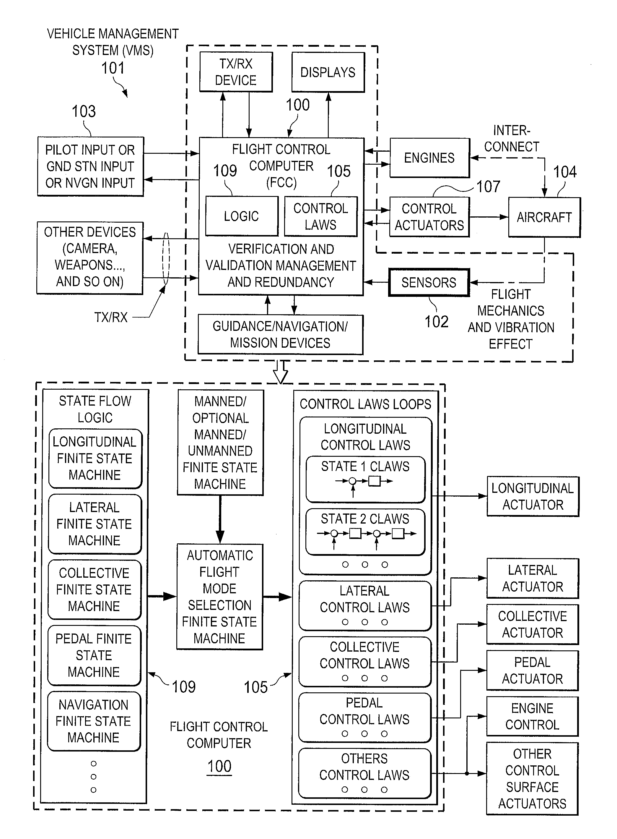
  • Vehicle management system using finite state machines
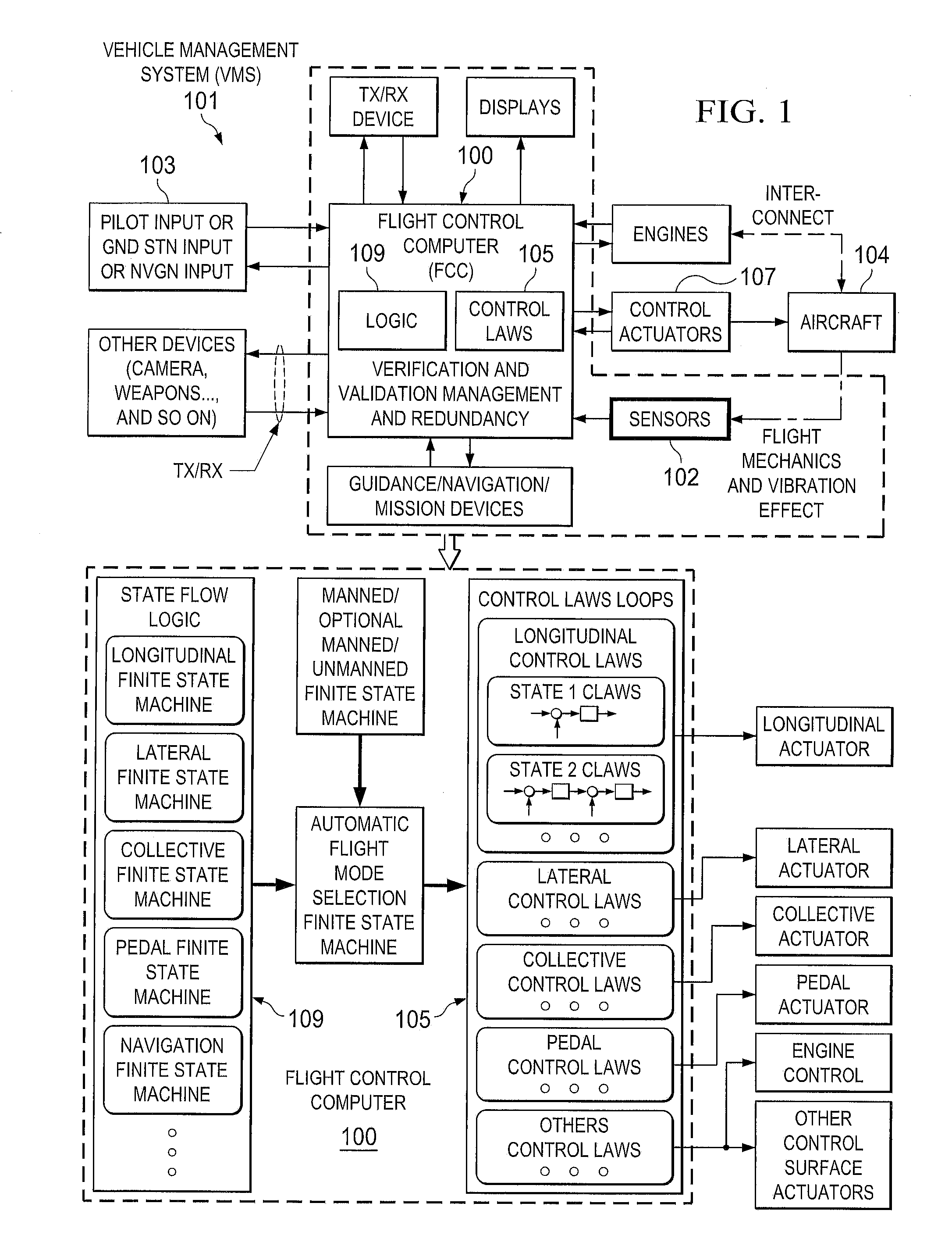
  • Vehicle management system using finite state machines
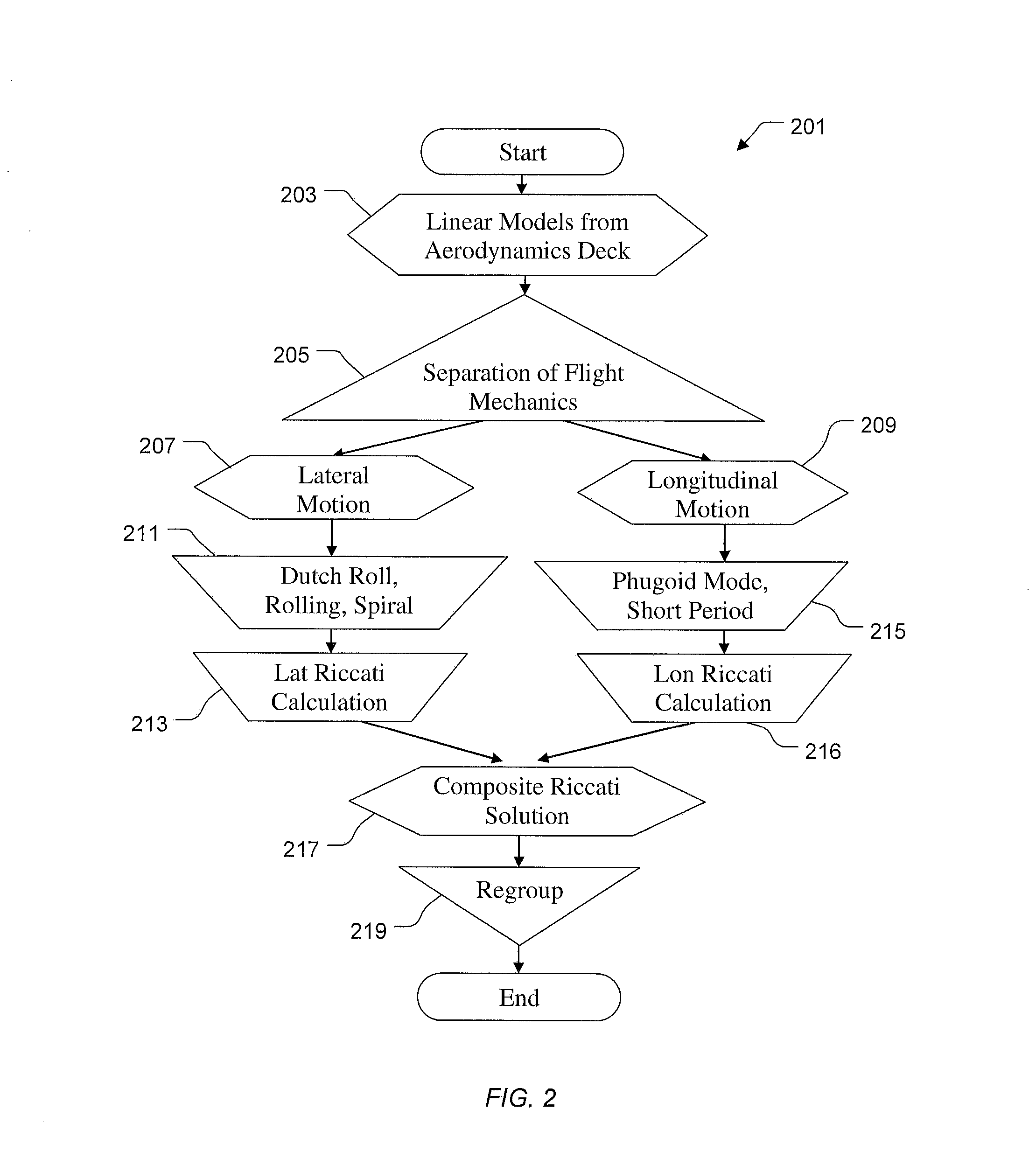
  • Vehicle management system using finite state machines

Examples


Embodiment Construction

[0038]Illustrative embodiments of the system and method are provided below. It will of course be appreciated that in the development of any actual embodiment, numerous implementation-specific decisions will be made to achieve the developer's specific goals, such as compliance with system-related and business-related constraints, which will vary from one implementation to another. Moreover, it will be appreciated that such a development effort might be complex and time-consuming, but would nevertheless be a routine undertaking for those of ordinary skill in the art having the benefit of this disclosure.

[0039]The system and method of the present application will be understood, both as to its structure and operation, from the accompanying drawings, taken in conjunction with the accompanying description. Several embodiments of the system are presented herein. It should be understood that various components, parts, and features of the different embodiments may be combined together and / or...


PUM


Abstract

A system includes a plurality of actuators and a management system operably associated with the plurality electronic and mechanical devices. The management architecture includes interfaces configured to the entire electronics and mechanics to provide a parameter to a computer. The computer includes a control and management architecture using modular finite state flow designs configured to analyze the parameter. The computer with a plurality of finite state machines can conduct a plurality of control laws operably associated with one or more actuators for finite functions of mobility. The method includes matching the parameter with the finite state machine and controlling the actuator via control law operably associated with finite state machine. The method can therefore be achieved either manually, semi-autonomously and autonomously with seamless and switchless control using a central control computer with integration of electronic and mechanic sensors and devices.

Description

BACKGROUND[0001]1. Field of the Invention[0002]The present application is directed to flight control law architectures for unmanned and manned aircraft.[0003]2. Description of Related Art[0004]Conventional aircraft control designs generally include one or more of a feedback gain and logic design which are utilized to switch between control loops with switches and / or buttons. The logic design utilizes the classic logic tree so that the flight control computer (FCC) and vehicle management system (VMS) architecture will be effective for maneuvering flights. An autopilot design will then be implemented by the third party to make aircraft to fly all kinds of hold mode. This design is strictly limited to manned type of the flight control system. Unmanned and optionally manned types of flight cannot be conducted with this kind of design.[0005]A common objective of semi-autonomous operation for the future vertical lift (FVL) of defense vertical take-off and landing aircraft (VTOL) has broug...

Claims


Application Information

Patent Timeline
Patent Type & Authority Patents(United States)
IPC IPC(8): B64C19/00
CPCG05D1/0858G05B2219/23289G05D1/0088B64C19/00
Inventor SHUE, SHYHPYNG JACKSHILLINGS, JOHN J.
Owner TEXTRON INNOVATIONS
Learn More