
Determining angular rate for line-of-sight to a moving object, with a body-fixed imaging sensor

a technology of line-of-sight and imaging sensor, which is applied in the direction of image enhancement, navigation instruments, instruments, etc., can solve the problems of insufficient high-performance interception sensors, inability to escape or mitigate efforts, and the requirement of very costly inertial-rate sensors or precise gimbals, so as to achieve the effect of low cost and less cos

Active Publication Date: 2015-02-03
ARETE ASSOCIATES INC
View PDF24 Cites 41 Cited by
  • Summary
  • Abstract
  • Description
  • Claims
  • Application Information

AI Technical Summary

Benefits of technology

The invention avoids the use of expensive and bulky inertial sensors for measuring body rate by using image-collecting sensors that are cheaper, lighter, and smaller. This leads to a reduction in cost, weight, and space requirements for high-bandwidth measurement.

Problems solved by technology

If of low cost, such sensors are not adequate for high-performance interception of moving, accelerating objects: such pursuit requires high-bandwidth guidance, which in turn is precluded by parasitic body coupling and measurement noise.
Hence these efforts fail to escape or mitigate the above-discussed requirement for very costly inertial-rate sensors or precise gimbals.

Method used


Image

  • Determining angular rate for line-of-sight to a moving object, with a body-fixed imaging sensor
  • Determining angular rate for line-of-sight to a moving object, with a body-fixed imaging sensor
  • Determining angular rate for line-of-sight to a moving object, with a body-fixed imaging sensor

Examples


Embodiment Construction

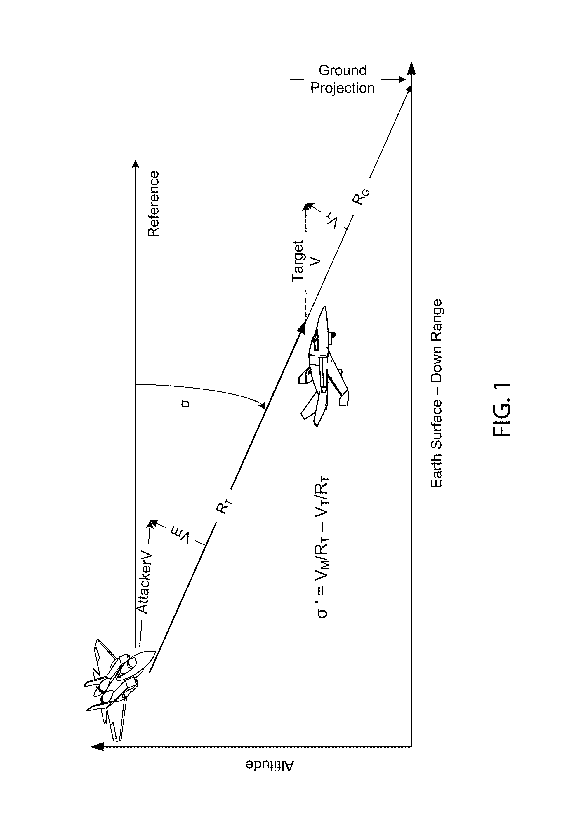
[0096]The main characteristics and behaviors of preferred embodiments of our present invention will next be introduced by way of analyzing two very general examples: tracking a generic (but noncooperative) moving object, and tracking a generic airborne object. Both these exercises are performed by an unmanned airborne vehicle (“UAV”):

[0097]1) UAV to Noncooperative-Moving-Object Example

[0098]Many practical problems present the task of pursuing or rendezvousing with vehicles or other objects that may be in motion. Among these, merely by way of illustration and without at all attempting to be exhaustive, are air-traffic control, fully automatic drive-by-wire multivehicle highway operations, astronautical docking, military encounters, and delivering airdrops of food or the like to a remote very small region (e.g. a “desert island”).

[0099]Military agencies often face the task of acquiring and neutralizing noncooperative objects while the latter are mobile. In the most modern of current-d...


PUM


Abstract

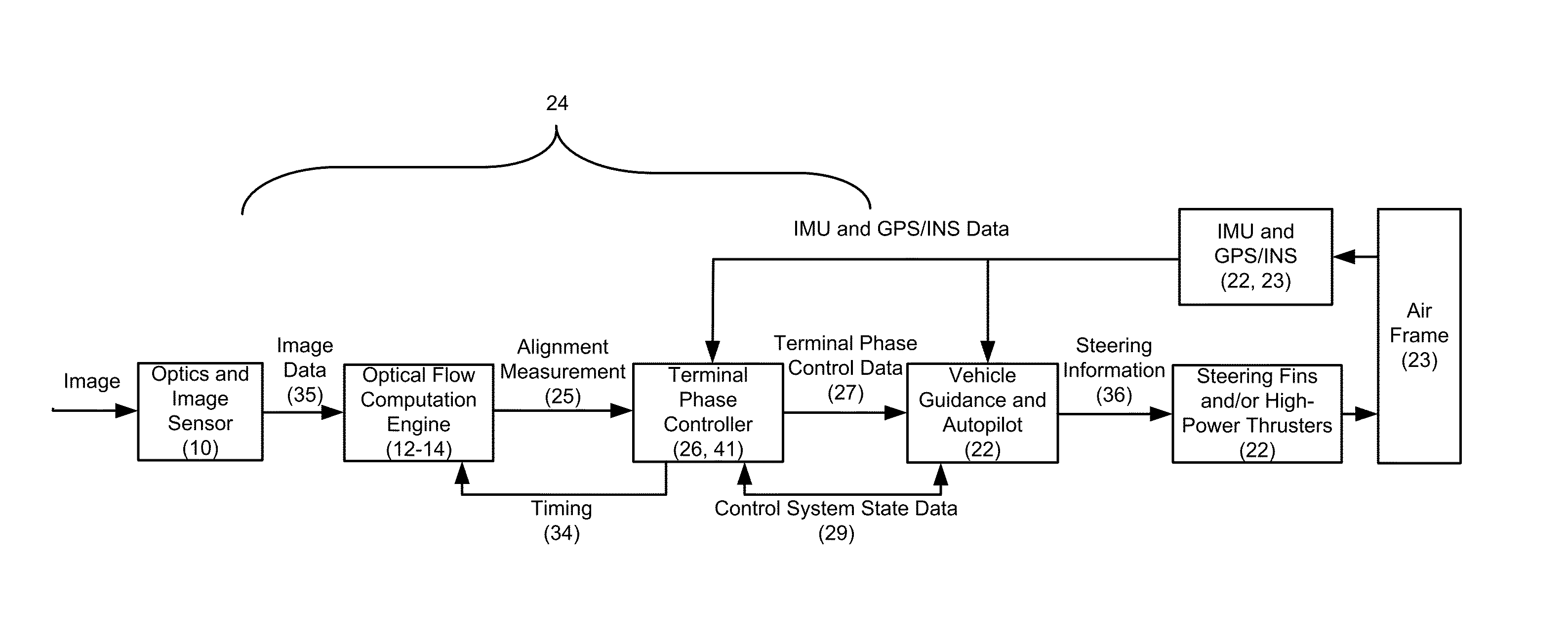
Apparatus / method estimate LOS rotation, to track, approach, pursue, intercept or avoid objects. Vehicle-fixed imagers approach / recede-from objects, recording image series with background. Computations, from images exclusively, estimate rotation vs. the vehicle, applying the estimate. Preferably, recording / estimating provide proportional navigation; scan mirrors extend strapdown-sensor FOR; applying includes measuring “range rate over range”, exclusively from interimage optical flow, using results to optimize proportional-navigation loop gain; estimating includes evaluating interframe optical flow, preregistering roughly as first approximation, selecting sequence anchor points, and applying a second, finer technique developing output registration that's a coordinate translation, aligning inertial surroundings. The approximation operates optical flow with efficient embedded registration / mapping, applying a homography matrix to nearby imagery. Alternatively, inexpensive low-quality inertial sensors establish preregistration, deriving a homography matrix. When contrast in the object direction is inadequate, dual sensors yield accurate virtual imaging with an object centroid superposed into background.

Description

RELATION BACK[0001]This patent document claims priority of U.S. Provisional Patent Application 61 / 208,830, filed Feb. 27, 2009. The present patent document is also a continuation-in-part, and accordingly claims priority, of non-provisional U.S. patent application Ser. No. 12 / 383,638, filed Mar. 25, 2009—which in turn claimed priority of U.S. Provisional Patent Application 61 / 072,028, filed Mar. 26, 2008. We have substantially copied into this present document certain parts of the precursor '638 application, and re-serve the right to likewise copy hereinto all or any part(s) of any of the three applications just mentioned.FIELD OF THE INVENTION[0002]Our invention relates generally to methods for guidance and control of a vehicle that is intended to rendezvous with or intercept an object—usually but not necessarily an object that is moving—and more specifically to such methods in which the control function is of a type known as “proportional navigation”. A fundamental principle of suc...

Claims


Application Information

Patent Timeline
Patent Type & Authority Patents(United States)
IPC IPC(8): F41G7/22F42B15/01F41G9/00F42B15/00F41G7/00
CPCF41G7/2246F41G7/2253F41G7/2286F41G7/2293F42B15/01G01C21/20G01C21/3602G01S3/784G01S11/12G01S13/89G01S17/89G06T2207/10016G06T2207/30212G06T2207/30252G06T7/269G06T7/70
Inventor DENNISON, JOHN CHARLESDAVIS, CLAYTON HOUSTONFRAZIER, BRIAN EDWARD
Owner ARETE ASSOCIATES INC
Learn More