Diffractive optical element, optical system, and optical apparatus
a technology of optical elements and optical elements, applied in the field of diffractive optical elements, optical systems, optical apparatus, can solve the problems of insufficient unnecessary light (flare), unnecessary light, etc., and achieve the effect of restraining unnecessary ligh
- Summary
- Abstract
- Description
- Claims
- Application Information
AI Technical Summary
Benefits of technology
Problems solved by technology
Method used
Image
Examples
first embodiment
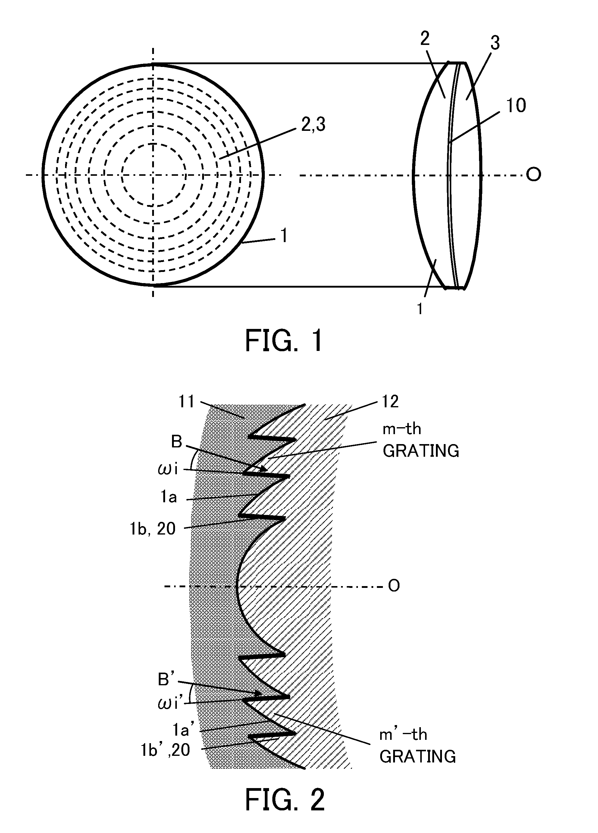
[0038]FIG. 1 illustrates a plane view and a side view of a diffractive optical element (“DOE”) 1 according to a first embodiment. The DOE 1 is configured to improve diffraction efficiency of diffracted light of one specific or designed order in a working wavelength range in an overall visible wavelength range.
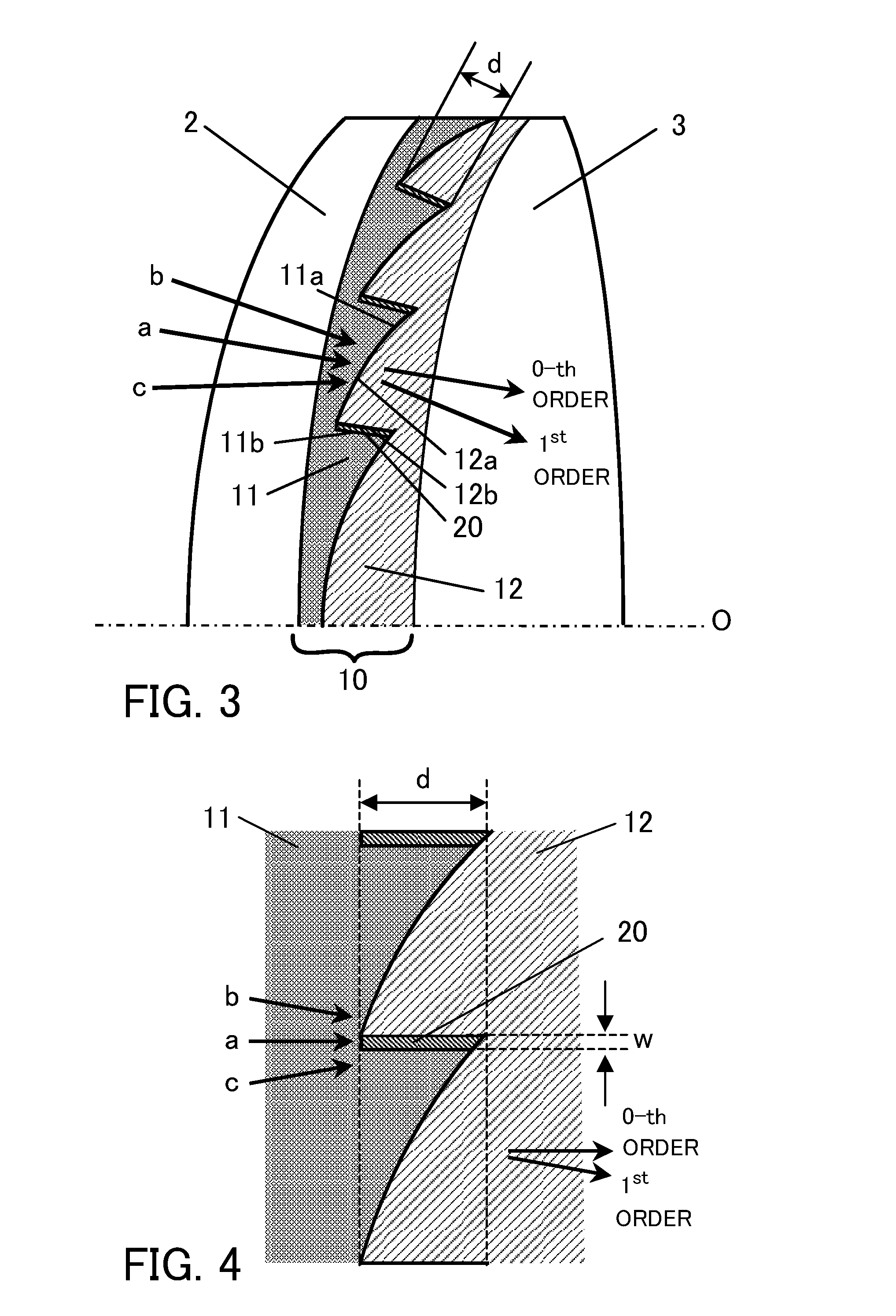
[0039]The DOE 1 includes a pair of transparent substrates 2 and 3, and a diffraction grating unit 10 arranged between them. While each of the substrates 2 and 3 may have a flat plate shape or a lens serving shape, each of top and bottom surfaces of the substrate 2 and top and bottom surfaces of the substrate 3 has a curved surface in this embodiment.
[0040]The diffraction grating unit 10 has a concentrical diffraction grating shape with the optical axis O as a center, and provides a lens operation. FIG. 2 is a partially enlarged sectional view near the center part of FIG. 1. FIG. 3 is a partially enlarged perspective view of the diffraction grating unit 10. FIG. 4 is an enlarged...
second embodiment
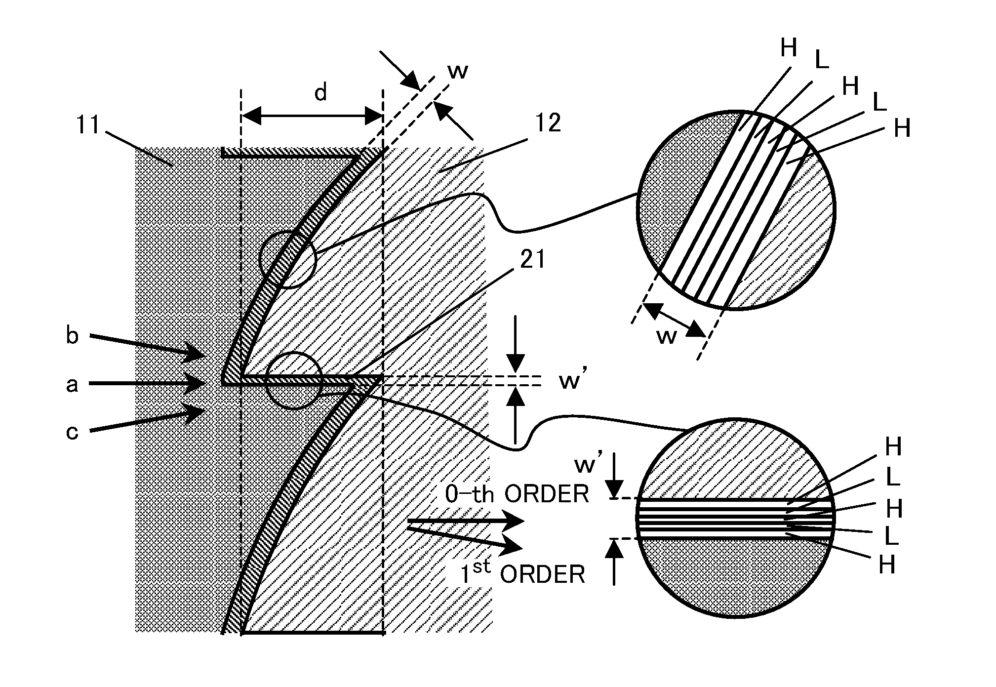
[0095]A second embodiment is similar to the first embodiment but is different from the first embodiment in that a width w of the thin film is 1.0 μm rather than 0.1 μm.
[0096]FIG. 15 is a graph of an RCWA calculation result with an incident angle of +10°, a grating pitch of 100 μm, and a wavelength of 550 nm by supposing the incident light flux “b” illustrated in FIG. 4 and the incident light flux “B” illustrated in FIG. 6.
[0097]The +1st order diffracted light as the designed order provides the highest diffraction efficiency, but this +1st order diffracted light never reaches the image plane and its influence is small. Similar to the first embodiment, the remaining unnecessary light becomes unnecessary light having a peak in the specific angle direction and propagates.
[0098]The peak angle of the unnecessary light in the −10° direction is almost the same as that in FIG. 8B, the spread of the unnecessary light is different between FIG. 15 and FIG. 8B. The diffraction efficiency at the ...
third embodiment
[0113]A third embodiment is different from the first embodiment in that the thin film 20 is made of Ta2O5 (n=2.154) and other than that, the third embodiment is similar to the first embodiment.
[0114]FIG. 18 is a graph of an RCWA calculation result with an incident angle of +10°, a grating pitch of 100 μm, and a wavelength of 550 nm by supposing the incident light flux “b” illustrated in FIG. 4 and the incident light flux “B” illustrated in FIG. 6.
[0115]The +1st order diffracted light as the designed order provides the highest diffraction efficiency, but this +1st order diffracted light never reaches the image plane and its influence is small. Similar to the first embodiment, it is understood that the remaining unnecessary light becomes unnecessary light having a peak in the specific angle direction and propagates.
[0116]The peak angle of the unnecessary light in the −10° direction is approximate the same as that of FIG. 8B, but a spread of the unnecessary light is different between F...
PUM
 Abstract
Description
Claims
Application Information
 - R&D
- Intellectual Property
- Life Sciences
- Materials
- Tech Scout
- Unparalleled Data Quality
- Higher Quality Content
- 60% Fewer Hallucinations
Browse by: Latest US Patents, China's latest patents, Technical Efficacy Thesaurus, Application Domain, Technology Topic, Popular Technical Reports.
© 2025 PatSnap. All rights reserved.Legal|Privacy policy|Modern Slavery Act Transparency Statement|Sitemap|About US| Contact US: help@patsnap.com


