
Optical apparatus, in-vehicle system, and mobile apparatus

a technology of optical equipment and in-vehicle system, applied in the field of optical equipment, can solve the problems of inability to accurately measure the distance to the object, difficulty in distinguishing unnecessary light and reflected light from each other, etc., and achieve the effect of reducing unnecessary ligh

Pending Publication Date: 2021-09-30
CANON KK
View PDF7 Cites 0 Cited by
  • Summary
  • Abstract
  • Description
  • Claims
  • Application Information

AI Technical Summary

Benefits of technology

The present invention provides optical devices, in-vehicle systems, and mobile devices that can prevent unwanted light from getting in the eyes of photodetector elements.

Problems solved by technology

In particular, it is difficult to distinguish the unnecessary light and the reflected light from a short-distance object from each other because the reflected light from the object is received before the signal saturation caused by the unnecessary light is reset.
As a result, the distance to the object cannot be accurately measured.

Method used


Image

  • Optical apparatus, in-vehicle system, and mobile apparatus
  • Optical apparatus, in-vehicle system, and mobile apparatus
  • Optical apparatus, in-vehicle system, and mobile apparatus

Examples


first embodiment

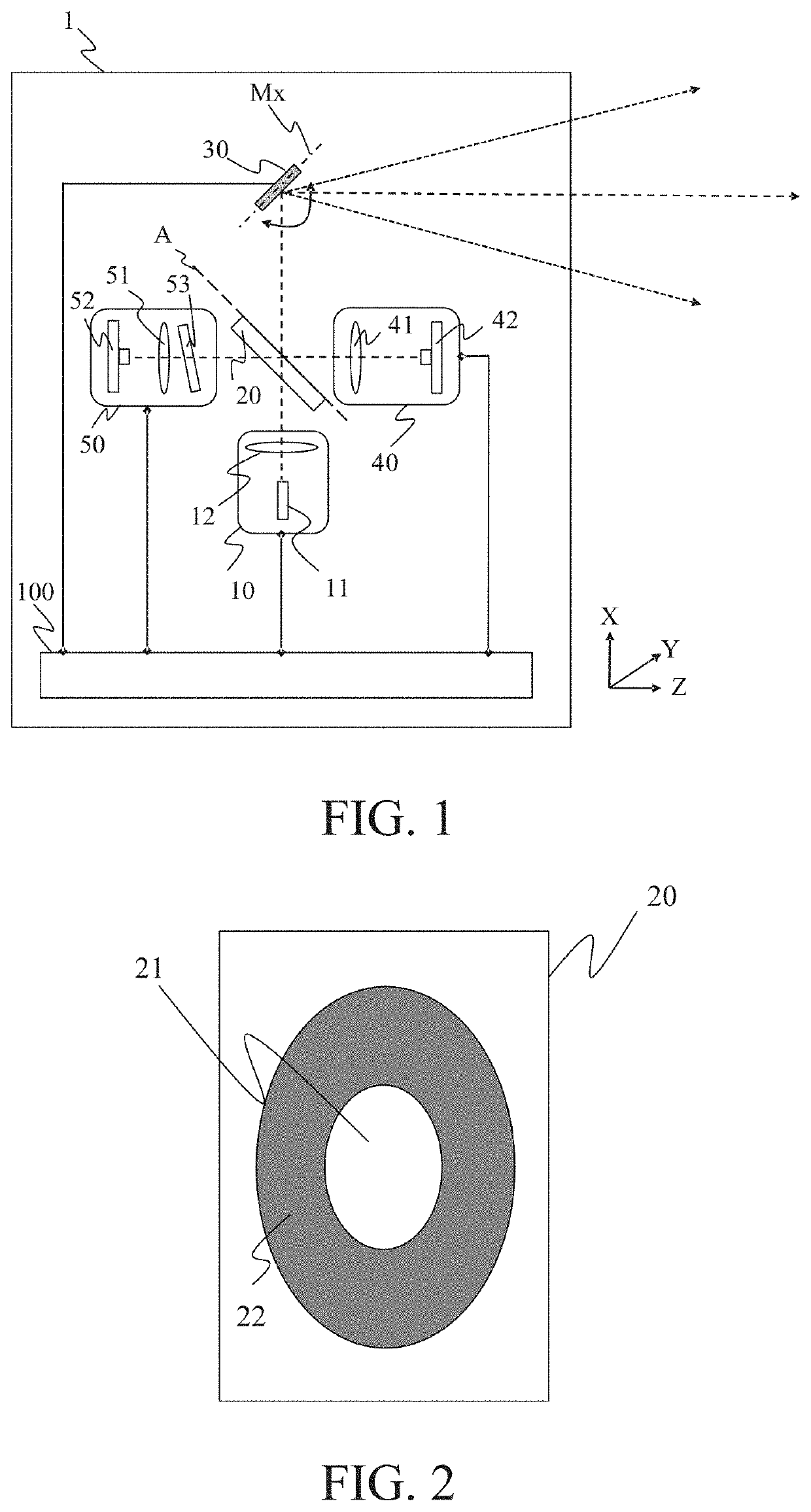
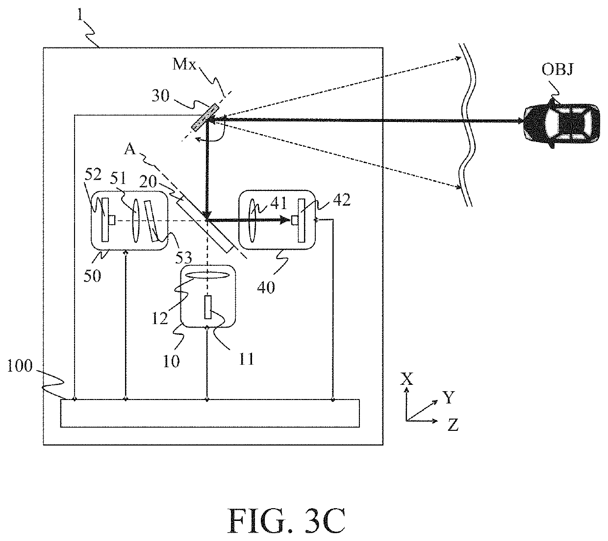
[0022]FIG. 1 is a schematic view of a distance measuring apparatus (optical apparatus) I according to this embodiment. The distance measuring apparatus 1 includes a light source unit 10, a splitter (light guide) 20, a drive mirror (deflector) 30. a first detector 40, a second. detector 50, and a controller 100.

[0023]The light source unit 10 includes a light source 11, and a collimator 12 that makes divergent light from the light source 11 substantially parallel light,

[0024]The drive mirror 30 is a two-dimensional scanning drive mirror that is rotationally driven around an axis parallel to a Y axis that passes the center of the mirror and an Mx axis indicated by an alternate long and short dash line and orthogonal the Y axis. The drive mirror 30 deflects the illumination light from the light source unit 10 so as to scan the object (object), and deflects the reflected light from the object so as to guide the light to the splitter 20.

[0025]The splitter 20 guides part of the illuminatio...

second embodiment

[0039]FIG. 5 is a schematic view of a distance measuring apparatus I according to this embodiment. The distance measuring apparatus I according to this embodiment is different from the distance measuring apparatus I in the first embodiment in that the splitter 20 is not a flat plate shape but is a polyhedral prism having a plurality of surfaces, and in having a magnification varying optical system 60 disposed on the light emitting side of the drive mirror 30. The magnification varying optical system 60 has no refractive power in the overall system, and guides the illumination light from the drive mirror 30 to the object OBJ and guides the reflected light from the object OBJ to the drive mirror 30. Since other configurations are the same as those of the first embodiment, a detailed description thereof will be omitted.

[0040]FIG. 6 illustrates a relationship between the magnification varying optical system 60 and the drive mirror 30 and, in the configurations of FIG. 5, the configurati...


PUM

PropertyMeasurementUnit
reflectanceaaaaaaaaaa
tilt angleaaaaaaaaaa
sizeaaaaaaaaaa

Abstract

An optical apparatus includes a deflector configured to deflect illumination light from a light source unit so as to scan an object and configured to deflect reflected light from the object, a light guide configured to guide part of the illumination light from the light source unit to the deflector, another part to a first light receiving element, and the reflected. light from the deflector to a second light receiving element, and an optical element having an optical surface provided between the light guide and the second light receiving element. The optical surface tilts or is eccentric to a principal ray of the illumination light.

Description

BACKGROUND OF THE INVENTIONField of the Invention[0001]The present invention relates to an optical apparatus that detects an object by receiving reflected light from the illuminated object.Description of the Related Art[0002]LiDAR (Light Detection and Ranging) is one known method for measuring a distance to an object, and calculates the distance based on a receiving time of the reflected light from the illuminated object or a phase of the reflected light. Japanese Patent No. 4476599 discloses a configuration for measuring the position and distance of the object based on an angle of a deflector (drive mirror) when a light receiving element receives the light reflected from the object and a signal obtained from the light receiving element.[0003]An apparatus using LiDAR may use an optical system and a light receiving element used to detect the illumination timing and to measure an emission light amount, in addition to the optical system and light receiving element used to measure the d...

Claims


Application Information

Patent Timeline
Patent Type & Authority Applications(United States)
IPC IPC(8): G01S17/931G02B26/10G02B7/02B60T7/22B60Q9/00G01S17/08
CPCG01S17/931G02B26/10G02B7/02B60T2201/022B60Q9/008G01S17/08B60T7/22G02B26/101G02B26/0816G01S7/4811
Inventor KAWAKAMI, TOMOAKI
Owner CANON KK
Learn More