
Assembly formed by a bracket, a clip and a base for an orthodontic apparatus, and orthodontic apparatus comprising same

a technology of brackets and brackets, which is applied in the field of assembly formed by brackets and brackets, and the same is applied in the field of orthodontic apparatus comprising same, which can solve the problems of prohibitive weakening of the base, and it is not possible to limit oneself to reducing the maximum thickness of the base, so as to reduce the maximum thickness of the assembly and significantly affect the strength of the base

Inactive Publication Date: 2015-01-13
CUZIN JEAN FRANCOIS
View PDF33 Cites 13 Cited by
  • Summary
  • Abstract
  • Description
  • Claims
  • Application Information

AI Technical Summary

Benefits of technology

The invention is a bracket assembly for orthodontists that reduces the thickness of the assembly without affecting the strength of the base. The assembly includes a self-ligating bracket with a clip that moves over the bracket by executing a rotational movement. The base has a depression that allows the clip to fit snugly without affecting the strength of the base. The thicker parts of the clip are housed in the depression, which results in a progressive and only localized reduction in the thickness of the assembly. This design may be useful for orthodontists who require a bracket assembly with a thinner profile.

Problems solved by technology

However, as will be seen hereinbelow, it is not possible to limit oneself to reducing this thickness of the base in this support region.
The thinned part of the base should thus then have a large surface and this would weaken the base in a prohibitive manner.

Method used


Image

  • Assembly formed by a bracket, a clip and a base for an orthodontic apparatus, and orthodontic apparatus comprising same
  • Assembly formed by a bracket, a clip and a base for an orthodontic apparatus, and orthodontic apparatus comprising same
  • Assembly formed by a bracket, a clip and a base for an orthodontic apparatus, and orthodontic apparatus comprising same

Examples


Embodiment Construction

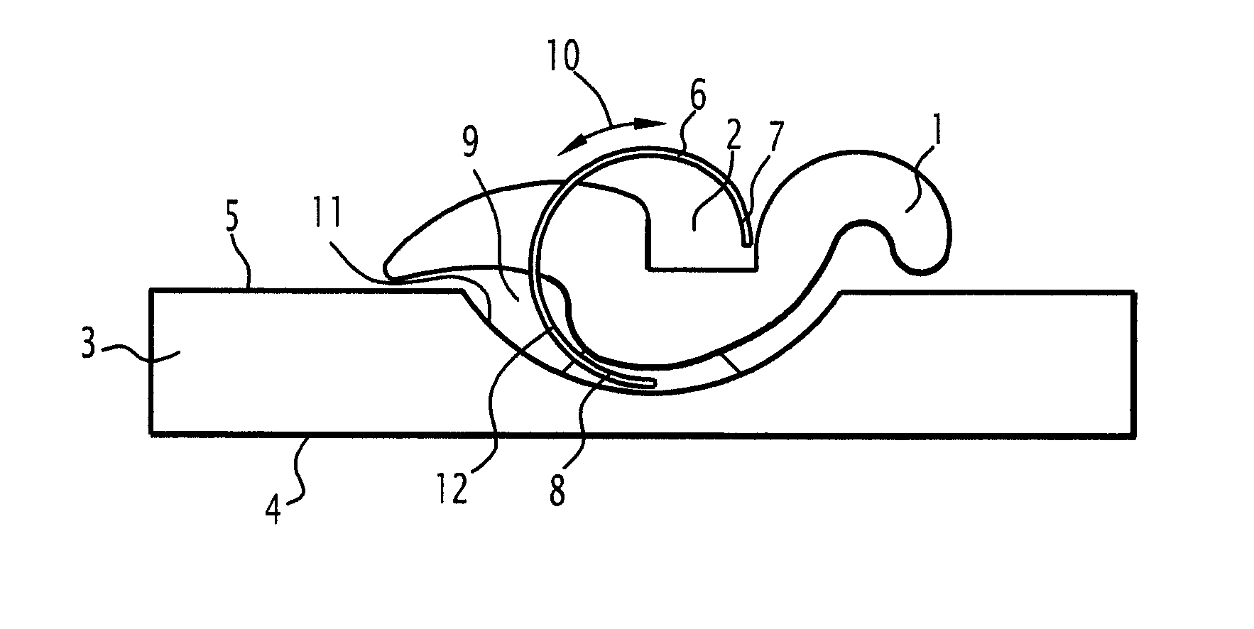
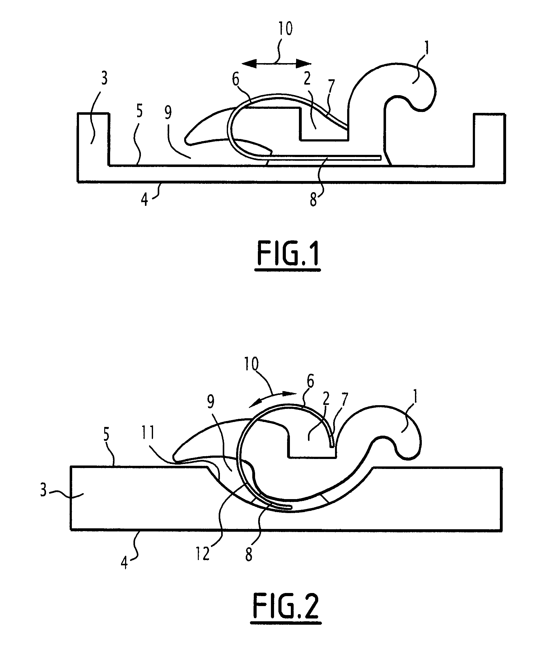
[0036]The terms “horizontal” and “vertical”, which will be employed in the rest of the description, will be used with reference to FIGS. 1 and 2 and to the position that the devices shown occupy therein, but it will be obvious for a person skilled in the art to transpose these terms to other positions of the devices.

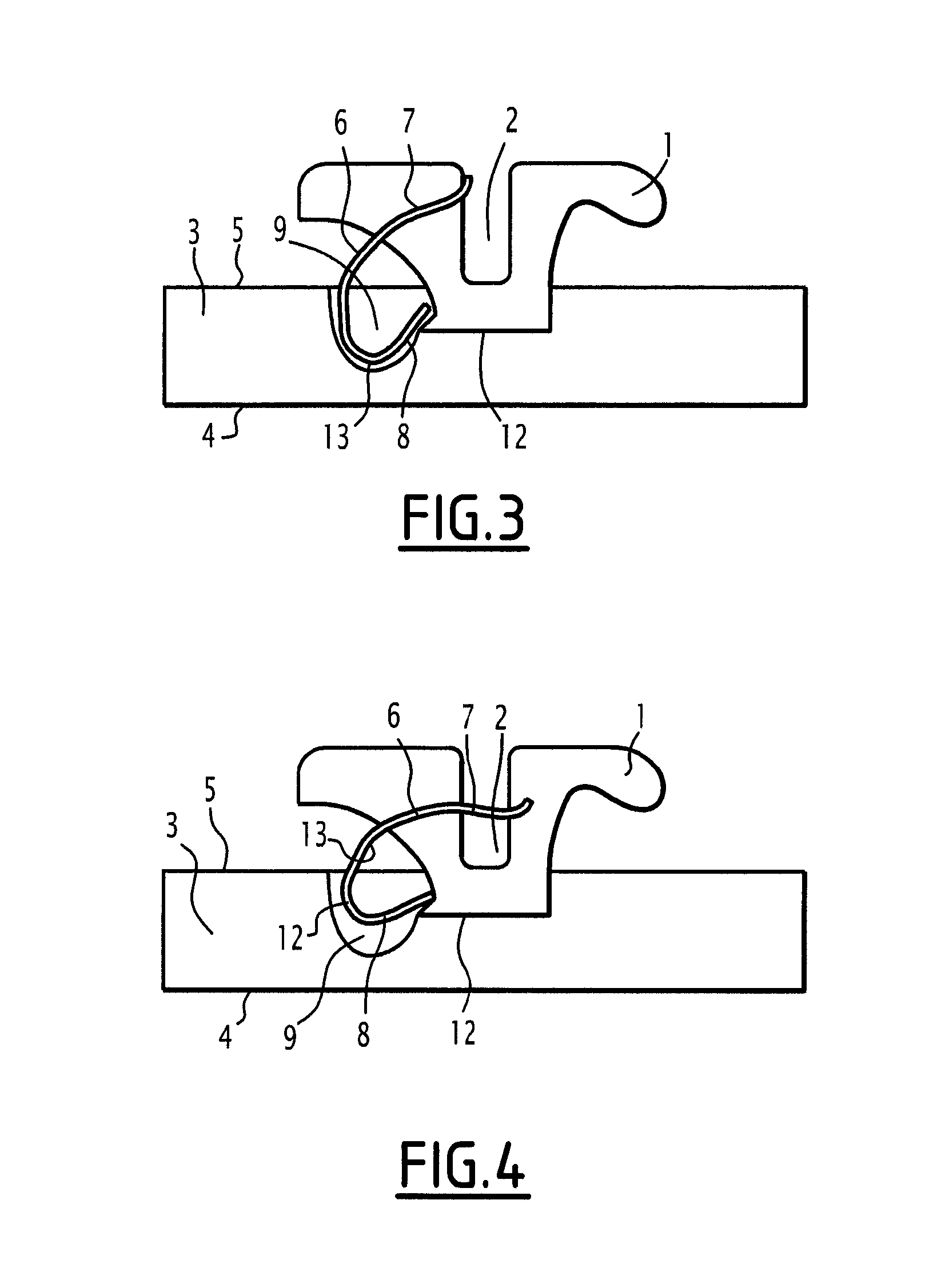
[0037]In the fictitious assembly in FIG. 1, which is not in accordance with the invention and is only illustrated to show that all the elements which will be mentioned below as part of the invention are indeed indispensable, the following elements are noted:[0038]a bracket 1 comprising on its outer face a groove 2 for the insertion of an orthodontic arch wire (not shown);[0039]a base 3, the occlusal face 4 of which is intended to be fixed to a lingual or vestibular face of a patient's tooth, and the outer face 5 of which carries the bracket 1;[0040]and an elastic clip 6 which is generally U-shaped in the example shown, a first arm 7 of which can close off the groove 2 an...


PUM


Abstract

An orthodontic assembly includes a self-ligating attachment having a groove for receiving an orthodontic arch. An elastic clip can be reversibly moved between an open position and a closed position sealing the groove. A base including an external surface and an occlusal surface, said external surface of the base supporting the attachment and said occlusal surface of the base being intended to rest on one of the patient's teeth. The aforementioned clip can be moved in an at least partially rotational manner between the open position and the closed position. Moreover, the area of the above-mentioned base that supports the attachment comprises a depression at least partially in the form of a cup and the clip is inserted into the depression when in the closed position.

Description

CROSS-REFERENCE TO RELATED APPLICATIONS[0001]This application is the U.S. national stage application of International Application PCT / EP2011 / 074093, filed Dec. 27, 2011, which international application was published on Jul. 5, 2012, as International Publication WO 2012 / 089731 in the French language. The International Application claims priority of French Patent Application 1061309, filed Dec. 28, 2010.BACKROUND[0002]The invention relates to a base / bracket assembly to be used in a customized orthodontic apparatus for treating a patient and intended mainly, but not exclusively, to be used in the case of a lingual technique, that is to say with the apparatus located on the non-visible posterior face of the teeth.[0003]Conventionally, such apparatuses comprise:[0004]at least one orthodontic arch wire, in other words a metal wire which exerts on the teeth a force that tends to move them from their unsatisfactory initial position, known as the “malposition”, into a satisfactory final posi...

Claims


Application Information

Patent Timeline
IPC IPC(8): A61C7/30A61C7/28
CPCA61C7/285A61C7/287A61C7/30
Inventor CURIEL, PATRICKSALAH, PHILIPPEAYACHE, WILLIAM
Owner CUZIN JEAN FRANCOIS
Learn More