
Porous polyurethane networks and methods of preparation

a polyurethane and porous technology, applied in the field of porous three-dimensional networks of polyurethane, can solve the problems of inability methods were unable to form gel networks, and methods were generally unable to control the early phase separation of nanoparticles from solvent solutions, so as to facilitate the phase separation of polyurethane particles

Active Publication Date: 2015-01-06
AEROGEL TECH
View PDF1 Cites 9 Cited by
  • Summary
  • Abstract
  • Description
  • Claims
  • Application Information

AI Technical Summary

Benefits of technology

This patent describes a way to make networks of polyurethane particles by mixing monomers together and adding a catalyst. The properties of these networks can be tailored by the type of monomers used. These networks can be used to create aerogels, which are materials with very small air bubbles. The patent explains how these networks can be used to improve the insulation of buildings or make sensors that detect changes in temperature or pressure.

Problems solved by technology

The inventors have recognized that previous methods of preparing three-dimensional porous polyurethane networks (e.g., polyurethane aerogels) resulted in mechanically weak networks having undesirably large pores and low surface areas.
Such methods were unable to form a gel network in which a substantial portion of the linkages between isocyanate and hydroxyl groups of the constituent monomers or oligomers are urethane linkages.
Such methods were also generally unable to control early phase separation of nanoparticles from the solvent solution to form a gel network with a high surface area.
Furthermore, previous methods were unable to control the density of reactive surface functional groups on the nanoparticles to form strong interparticle connections and thus form a network with strong mechanical properties.

Method used


Image

  • Porous polyurethane networks and methods of preparation
  • Porous polyurethane networks and methods of preparation
  • Porous polyurethane networks and methods of preparation

Examples


examples

[0081]The following examples are only provided as illustrative embodiments of the present invention and are meant to be non-limiting. As follows, polyurethane aerogels may be prepared using suitable methods described below.

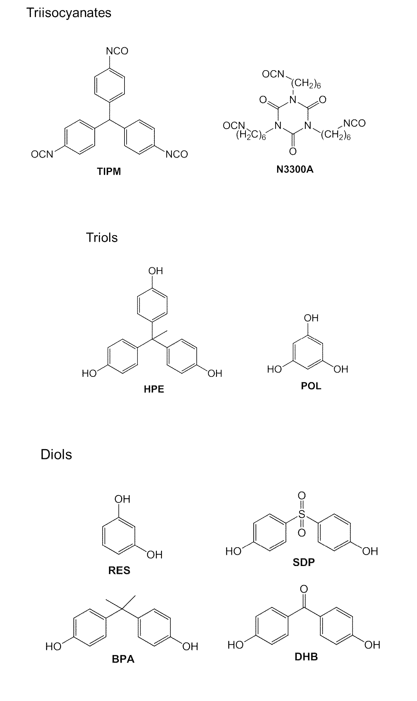
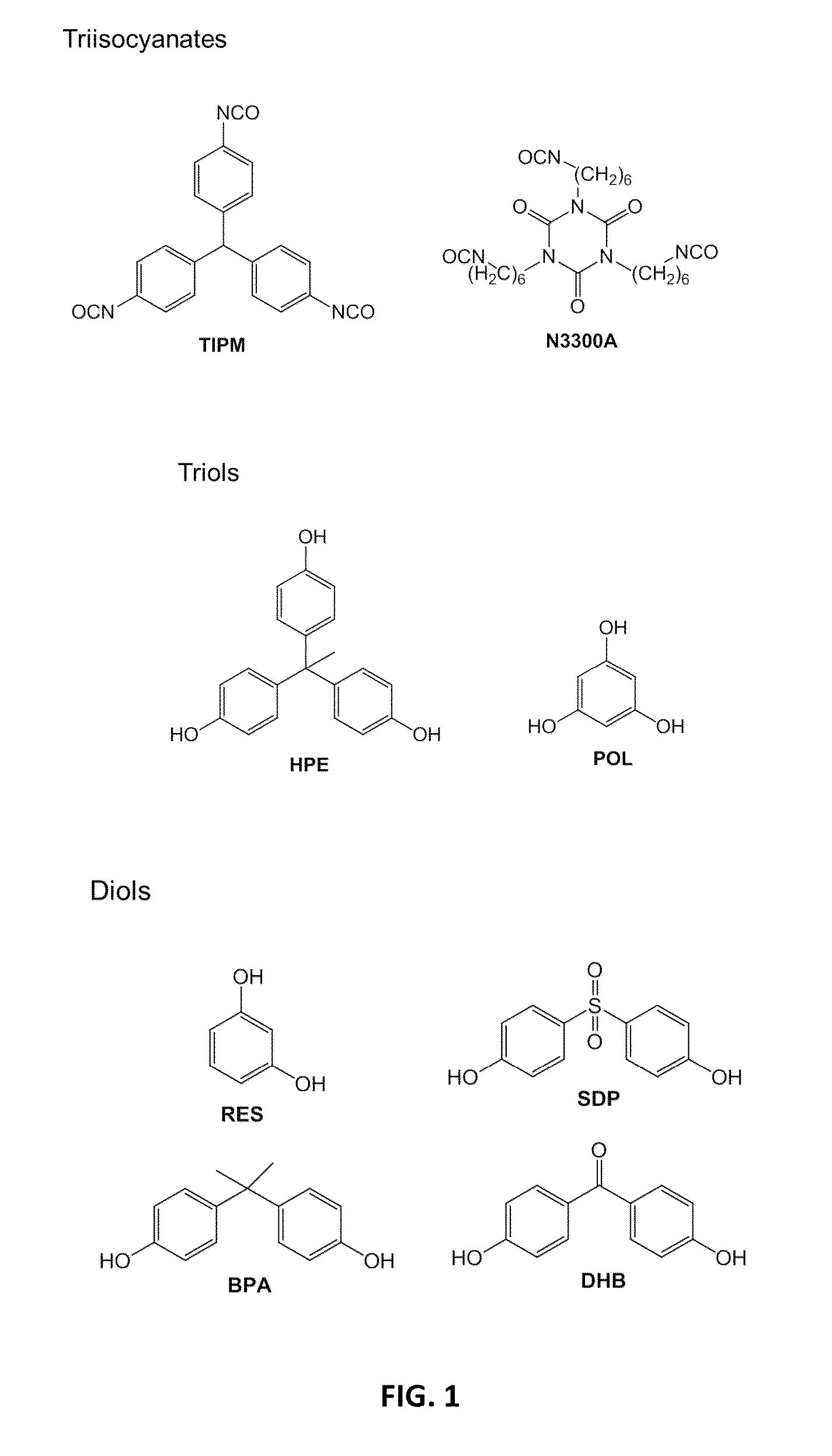
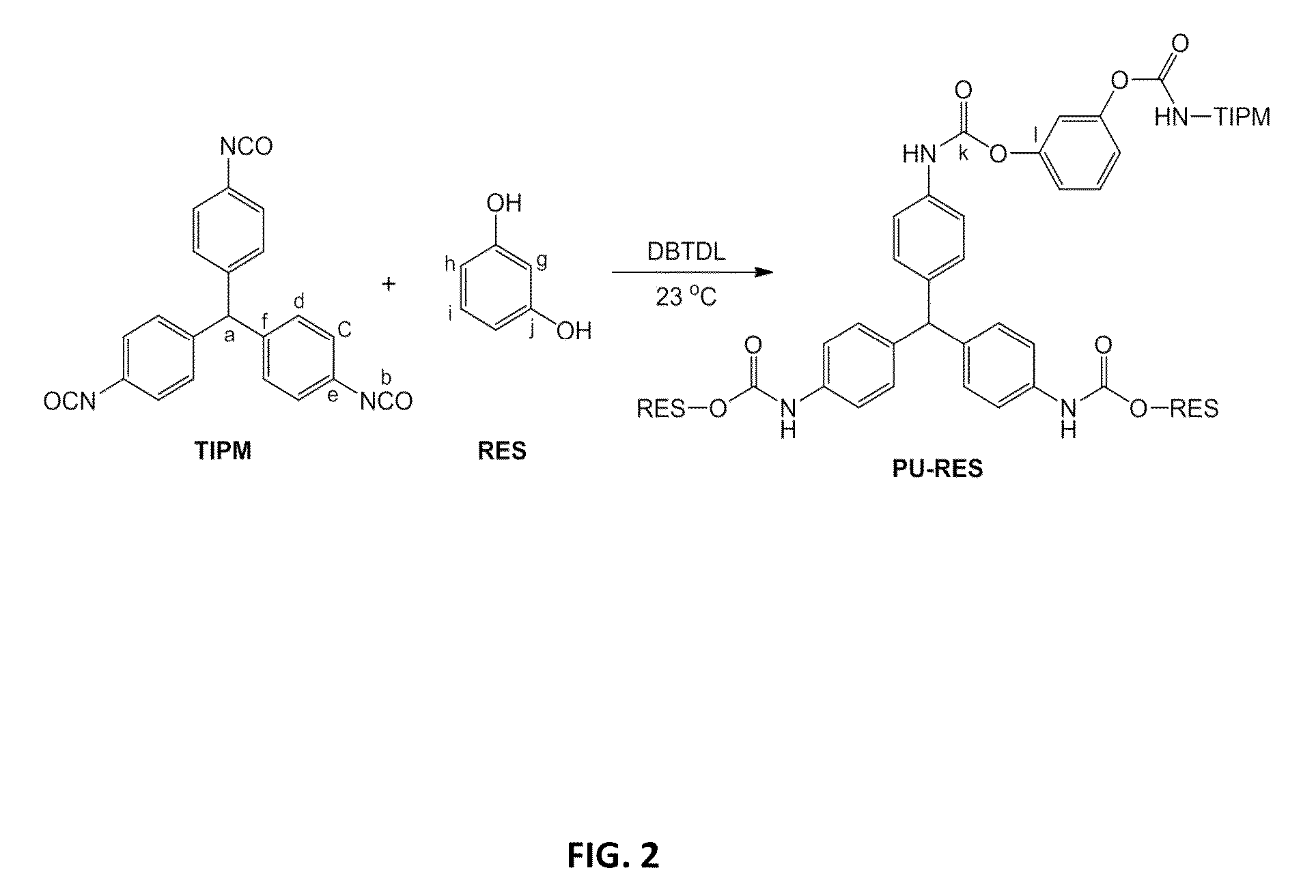
[0082]In the following examples, compositions are referenced by a part number that describes the small-molecule isocyanate monomer used, the small-molecule polyol monomer used, and the weight percent of the solution (% w / w) of total monomers used (i.e., the sum of the weight of the isocyanate and the weight of the polyol divided by the total solution weight, which may also include a solvent, a catalyst, etc.). Part numbers are of the form II-PP-xx, where “II” is an abbreviation for the isocyanate monomer used, “PP” is an abbreviation for the polyol monomer (alcohol) used, and “xx” is a number representing the % w / w of all monomers.[0083]“II”: The symbol “aR” represents the small-molecule monomer triisocyanate tris(isocyanatophenyl)methane (Desmodur RE, TIPM), wher...


PUM

PropertyMeasurementUnit
mean diameteraaaaaaaaaa
mean pore diameteraaaaaaaaaa
quasi-static uniaxial compressive modulusaaaaaaaaaa

Abstract

Nanoporous three-dimensional networks of polyurethane particles, e.g., polyurethane aerogels, and methods of preparation are presented herein. Such nanoporous networks may include polyurethane particles made up of linked polyisocyanate and polyol monomers. In some cases, greater than about 95% of the linkages between the polyisocyanate monomers and the polyol monomers are urethane linkages. To prepare such networks, a mixture including polyisocyanate monomers (e.g., diisocyanates, triisocyanates), polyol monomers (diols, triols), and a solvent is provided. The polyisocyanate and polyol monomers may be aliphatic or aromatic. A polyurethane catalyst is added to the mixture causing formation of linkages between the polyisocyanate monomers and the polyol monomers. Phase separation of particles from the reaction medium can be controlled to enable formation of polyurethane networks with desirable nanomorphologies, specific surface area, and mechanical properties. Various properties of such networks of polyurethane particles (e.g., strength, stiffness, flexibility, thermal conductivity) may be tailored depending on which monomers are provided in the reaction.

Description

FEDERALLY SPONSORED RESEARCH[0001]Research leading to various aspects of embodiments presented herein were sponsored, at least in part, by the National Science Foundation under Grant No. CHE-0809562 and the Army Research Office under Grant No. W911NF-10-1-0476. The United States Government may have certain rights in the invention.BACKGROUND[0002]1. Field[0003]Aspects herein relate to porous three-dimensional networks of polyurethane, uses thereof, and methods of preparation. For example, the porous networks of polyurethane may include a polyurethane aerogel material.[0004]2. Discussion of Related Art[0005]Aerogels are three-dimensional assemblies of nanoscale, nanostructured, or nanofeatured particles that are highly porous materials exhibiting ultra-low densities. Aerogel materials are typically produced by forming a gel containing a liquid component and a porous solid component and removing the liquid by supercritically or subcritically drying the wet gel to leave behind the porou...

Claims


Application Information

Patent Timeline
Patent Type & Authority Patents(United States)
IPC IPC(8): B29D22/00B29D23/00B32B1/08B65D39/00C01B31/02C08G18/06C08J9/28
CPCC08J9/286C01B31/02C08G18/06C08J2205/026C08J2205/042C08J2375/04C08J2201/04B01J20/20B01J20/267B01J20/28011B01J20/28042B01J20/28047B01J20/28057B01J20/28078B01J20/3078C04B38/0032C08G18/3215C08G18/3872C08G18/7657C08G18/792C08J2201/0502C01B32/00C01B32/05C08G2110/0091Y10T428/1376Y10T428/21Y10T428/24149Y10T428/2982Y10T428/249953Y10T428/249978Y10T428/249986Y10T428/31547C04B35/52C08G18/7664C08G18/7893
Inventor LEVENTIS, NICHOLASSOTIRIOU-LEVENTIS, CHARIKLIACHIDAMBARESWARAPATTAR, CHAKKARAVARTHY
Owner AEROGEL TECH
Learn More