
Therapy head for use with an ultrasound system

a technology of ultrasound system and therapy head, which is applied in the field of hand-held medical devices, can solve the problems of difficulty or inability for a person to either hold the device steady or the therapeutic means stationary, and achieve the effect of improving the therapeutic effect and increasing the accuracy

Active Publication Date: 2015-01-06
SOLTA MEDICAL
View PDF103 Cites 68 Cited by
  • Summary
  • Abstract
  • Description
  • Claims
  • Application Information

AI Technical Summary

Benefits of technology

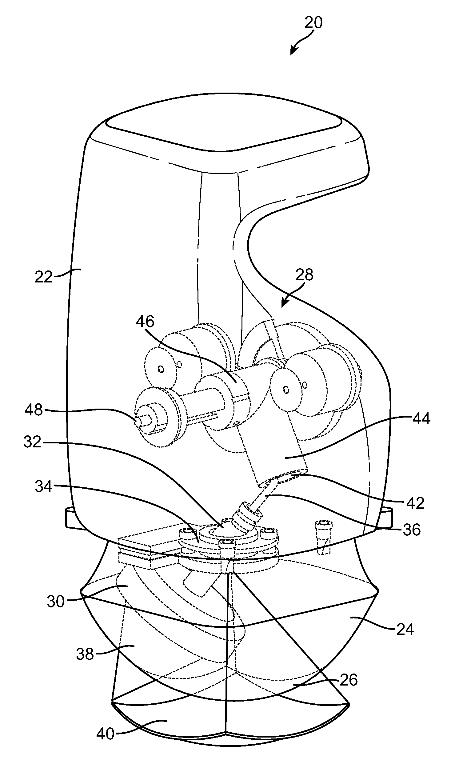
[0009]Hand held therapy heads and related medical systems are provided that include an actuation assembly for selectively directing the output of an directional energy applicator, such as an ultrasound transducer. Such selective direction can be used during ultrasound therapies to increase the accuracy by which the energy is delivered over a treatment region, which may result in improved therapeutic effect.

Problems solved by technology

A general problem in the application of high intensity focused ultrasound (HIFU) for therapeutic purposes is that it is often necessary to hold the therapeutic means stationary for some significant amount of time over the tissue to be treated.
Both of these requirements present a barrier to the use of hand-held therapeutic devices, as it is often difficult or impossible for a person to either hold the device steady, or to scan at an acceptably slow and steady rate for the desired therapeutic effect.
These requirements are beyond the capabilities of most human beings.
Such an arrangement has the disadvantages of size and bulk, complexity and reliability of the overall device.

Method used


Image

  • Therapy head for use with an ultrasound system
  • Therapy head for use with an ultrasound system
  • Therapy head for use with an ultrasound system

Examples


Embodiment Construction

[0032]In the following description, various embodiments of the present invention will be described. For purposes of explanation, specific configurations and details are set forth in order to provide a thorough understanding of the embodiments. However, it will also be apparent to one skilled in the art that the present invention may be practiced without the specific details. Furthermore, well-known features may be omitted or simplified in order not to obscure the embodiment being described.

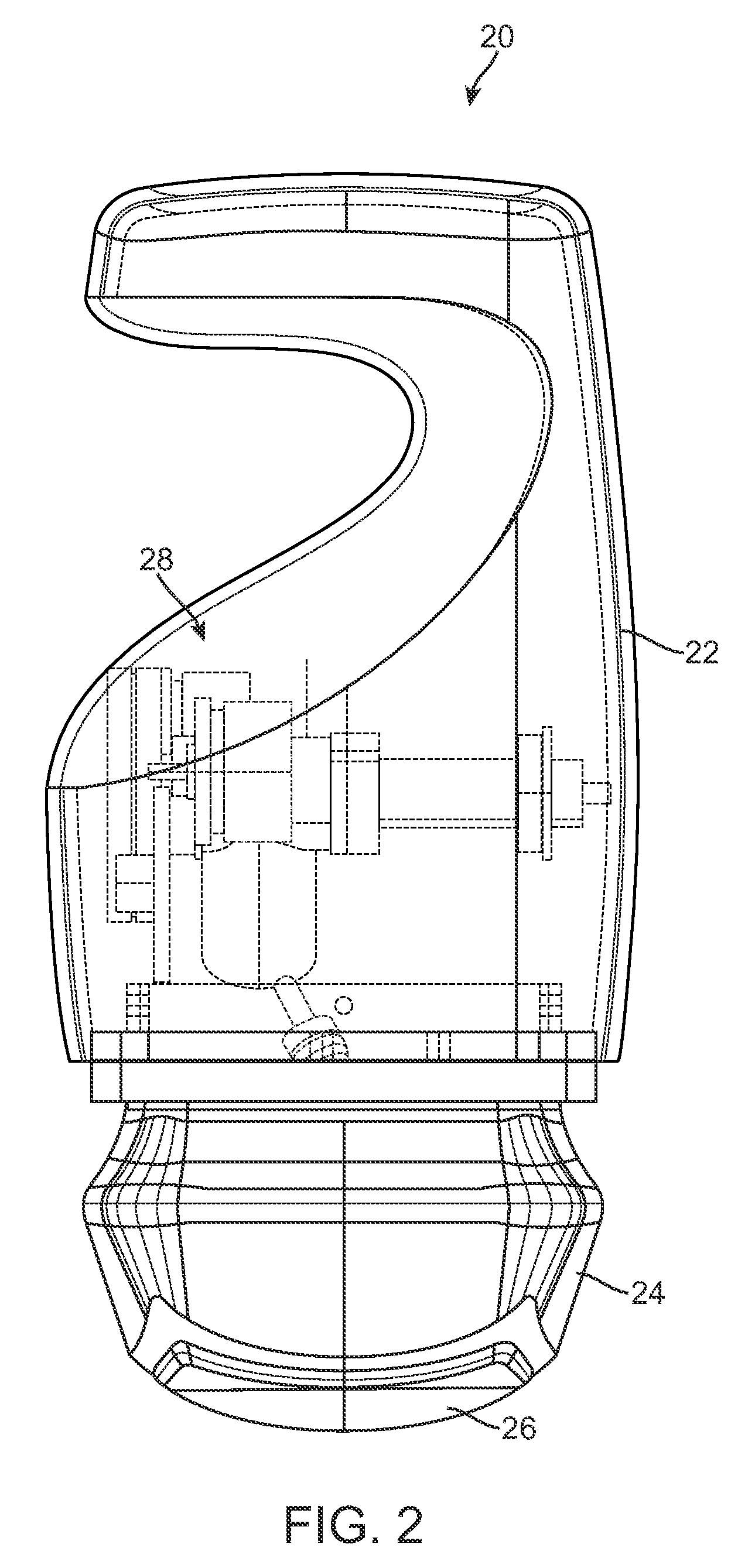
[0033]Described herein are various embodiments of a therapy head for use with a medical system. More particularly, therapy heads and related medical systems are provided that include an actuation assembly for selectively directing the output of an directional energy applicator, such as an ultrasound transducer.

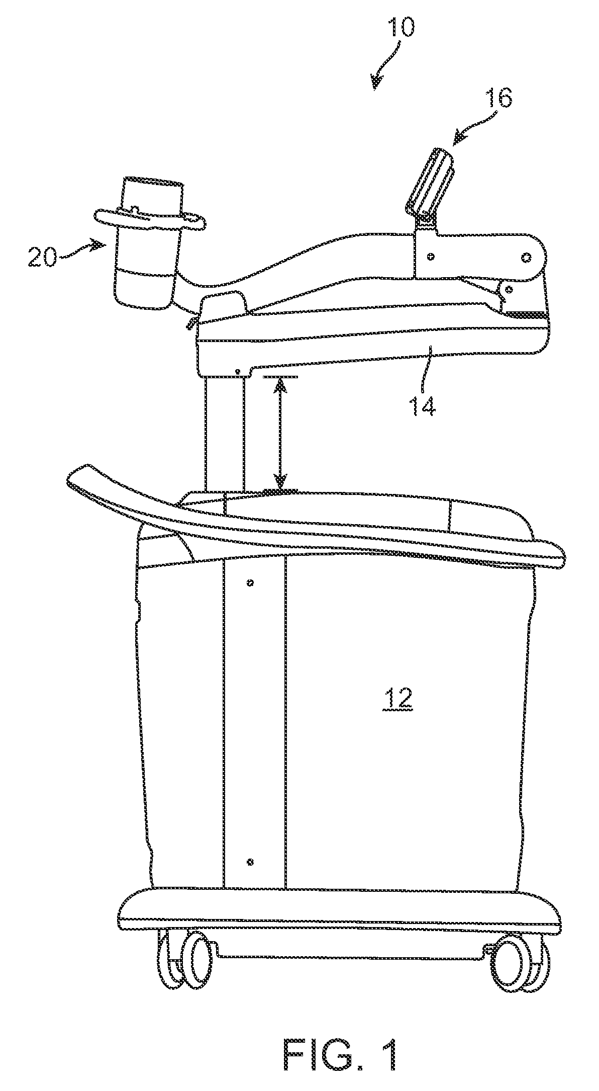
[0034]Referring now to the drawings, in which like reference numerals represent like parts throughout the several views, FIG. 1 shows a medical ultrasound system 10. The medical ultrasound s...


PUM


Abstract

Therapy heads and related medical systems having an actuation assembly for controlling the position / orientation of a directional energy applicator in at least two planes are disclosed. A therapy head includes an enclosure, a partition separating a lower compartment from an upper compartment, an aperture in the partition, a control arm extending through the aperture, an actuation assembly positioned within the upper compartment, and a directional energy applicator positioned in the lower compartment for transmitting energy through a window. The control arm includes an upper end disposed within the upper compartment and a lower end disposed within the lower compartment. The actuation assembly is coupled with the upper end of the control arm such that the control arm is movable by the actuation assembly in at least two planes. The directional energy applicator is coupled with the lower end of the control arm.

Description

CROSS-REFERENCES TO RELATED APPLICATIONS[0001]The present application is a continuation-in-part of application Ser. No. 11 / 027,912, filed on Dec. 29, 2004, which claims the benefit of provisional application No. 60 / 534,036, filed on Dec. 30, 2003, the full disclosures of which are incorporated herein by reference. The present application also claims the benefit of provisional application No. 61 / 025,618, filed on Feb. 1, 2008, the full disclosure of which is incorporated herein by reference.BACKGROUND[0002]The present invention relates generally to handheld medical devices for precisely delivering energy into a human body, and more particularly to handheld medical devices and related systems having an actuation assembly for controlling the position / orientation of a directional energy applicator in at least two planes. The position / orientation control provided can be especially beneficial when used in a medical ultrasound therapy head that is used for non-invasive therapies.[0003]A ge...

Claims


Application Information

Patent Timeline
Patent Type & Authority Patents(United States)
IPC IPC(8): A61H1/00A61B19/00A61H23/02A61N7/00A61N7/02
CPCA61N7/02A61B19/22A61H23/0245A61N2007/0008A61N2007/0091A61B2018/00464G10K11/352A61B34/70
Inventor BOCKENSTEDT, CRAIG ROBERTLITTLE, BLAKEALBRIGHT, ETHAN
Owner SOLTA MEDICAL
Learn More