
Method for monitoring the enabling of a system

a technology of enabling and monitoring system, applied in the direction of electrical control, exhaust treatment electric control, instruments, etc., can solve the problems of failure, fault, fault, etc., and achieve the effect of being ready to us

Active Publication Date: 2014-12-30
ROBERT BOSCH GMBH
View PDF5 Cites 2 Cited by
  • Summary
  • Abstract
  • Description
  • Claims
  • Application Information

AI Technical Summary

Benefits of technology

This approach provides more accurate and reliable monitoring of the SCR system's readiness, reducing the impact of temperature sensor inaccuracies and meeting regulatory requirements effectively.

Problems solved by technology

However, the use of RHU may not be appropriate under certain circumstances (e.g. warm starting, frozen reducing agent etc.).
If CL has not been achieved, a fault is set.
If operation of the system cannot be detected after the expiry of the second predeterminable time period either, the fault is set.

Method used


Image

  • Method for monitoring the enabling of a system
  • Method for monitoring the enabling of a system
  • Method for monitoring the enabling of a system

Examples


Embodiment Construction

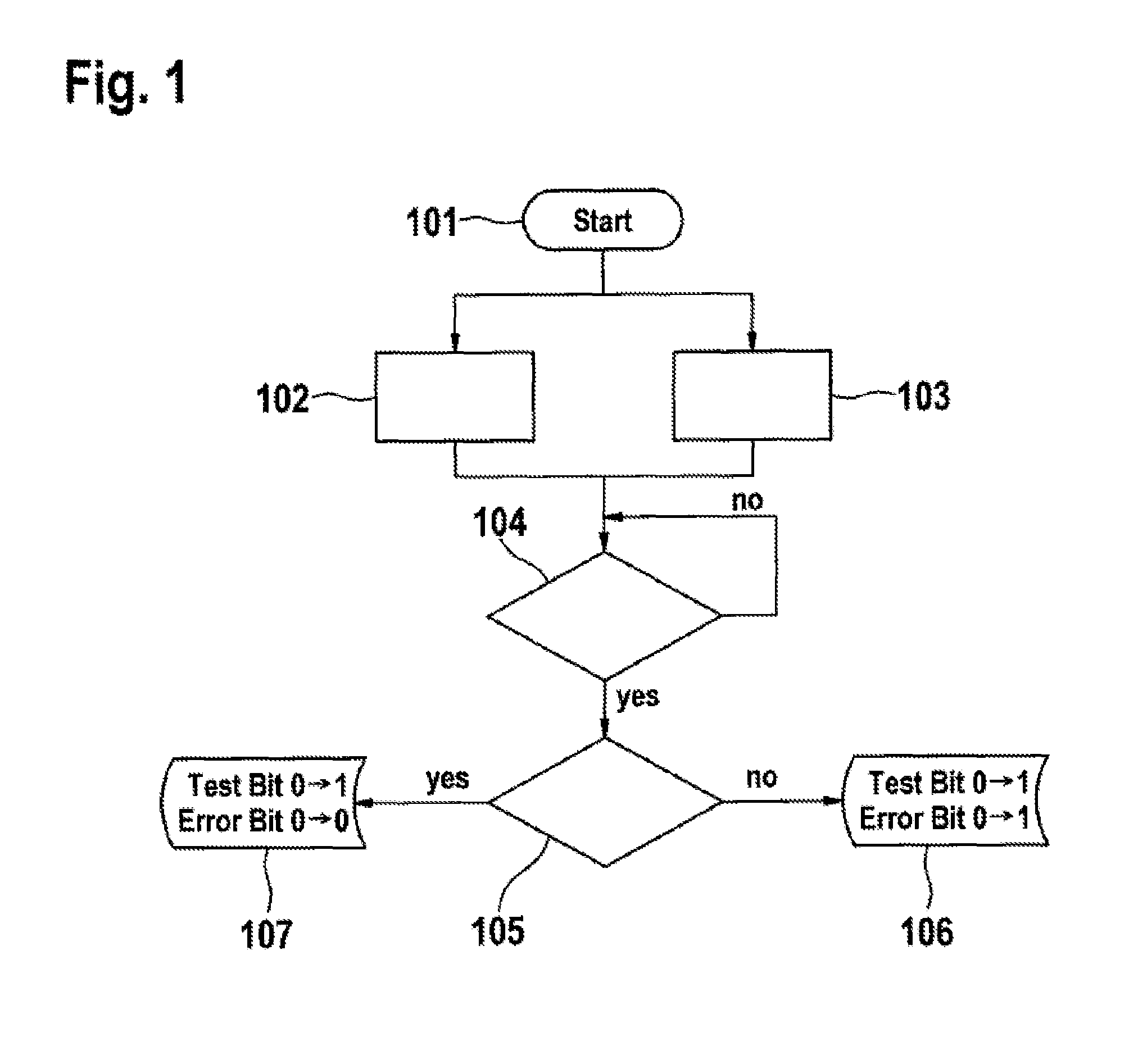
[0023]FIG. 1 shows a flow chart intended to illustrate one embodiment of the method according to the invention. After the starting 101 of the internal combustion engine, the timer is started in step 102 in order to record the time. In parallel with this, in step 103, the first time model relating to the attainment of the threshold value tStart is started. In step 104, a check is made to determine whether the threshold value tStart calculated by means of the first time model has been reached by the engine running time. If this is not the case, the program loops back to the start of step 104. If this is the case, a check is made, in step 105, to determine whether operation of the system can be detected, i.e. whether a closed control loop (CL), for example, of the SCR metering system, for example, can be detected. If operation cannot be detected, a fault is set (error bit 0→1) and a test bit is set to 1 (test bit 0→1) in the output 106. If, in step 105, the program ascertains that oper...


PUM


Abstract

A method for monitoring the enabling of a system which is assigned to an internal combustion engine, in which the readiness for operation of the system is dependent on an operating temperature, is characterized in that a fault in the enabling of the system is inferred (106) if operation of the system cannot be detected on expiry of a predeterminable time period after the starting of the internal combustion engine or on the recurrence of readiness for operation.

Description

BACKGROUND OF THE INVENTION[0001]The present invention relates to a method for monitoring the enabling of a system which is assigned to an internal combustion engine, in which the readiness for operation of the system is dependent on an operating temperature.[0002]In order to reduce nitrogen oxides in the exhaust gas of an internal combustion engine, use is already being made of so-called SCR catalytic converters (Selective Catalytic Reduction) in the exhaust section of the internal combustion engine to reduce the nitrogen oxides contained in the exhaust gas to nitrogen in the presence of a reducing agent. Ammonia is required for the reaction to take place, and this is added to the exhaust gas. In general, an aqueous urea solution is used for this purpose, being injected into the exhaust line upstream of the SCR catalytic converter with the aid of a metering device. Ammonia is formed from this solution and acts as a reducing agent.[0003]For optimum aftertreatment of the exhaust gas,...

Claims


Application Information

Patent Timeline
Patent Type & Authority Patents(United States)
IPC IPC(8): F01N3/02F02D41/22F02D41/14F01N11/00F01N9/00
CPCF02D41/22F01N2900/08F02D41/1466F01N3/0205F01N2900/1602Y02T10/40F01N2900/0421F01N2550/05F01N2900/0422Y02T10/47F01N11/002F01N9/005
Inventor BOUVIER, DAMIENPFISTER, TOBIASLINKE, JOERGKLUEVER, FRANK
Owner ROBERT BOSCH GMBH
Learn More