
Slide assembly with deceleration device

a technology of deceleration device and sliding assembly, which is applied in the direction of building braking device, door/window fitting, construction, etc., can solve the problems of reducing the reliability of the positioning device and the impact noise of the positioning device, so as to reduce the impact force and noise, slow down the pulling speed of the rail, and reduce the sliding speed of the rail

Active Publication Date: 2014-12-30
KING SLIDE WORKS CO LTD +1
View PDF15 Cites 13 Cited by
  • Summary
  • Abstract
  • Description
  • Claims
  • Application Information

AI Technical Summary

Benefits of technology

The present invention is a slide assembly with a deceleration device that reduces the speed of the rail when it is pulled to its fully extended position, to reduce impact force and noise. The deceleration device also creates a resistance effect for the user, allowing them to slow down the pull speed of the rail as they approach the fully extended position.

Problems solved by technology

However, these two conventional slide assemblies of the prior art do not have a deceleration device so that when the rails is pulled to a desired position by a significant force, the positioning device generates impact noise, and / or the reliability of the positioning device is decreased.

Method used


Image

  • Slide assembly with deceleration device
  • Slide assembly with deceleration device
  • Slide assembly with deceleration device

Examples


Embodiment Construction

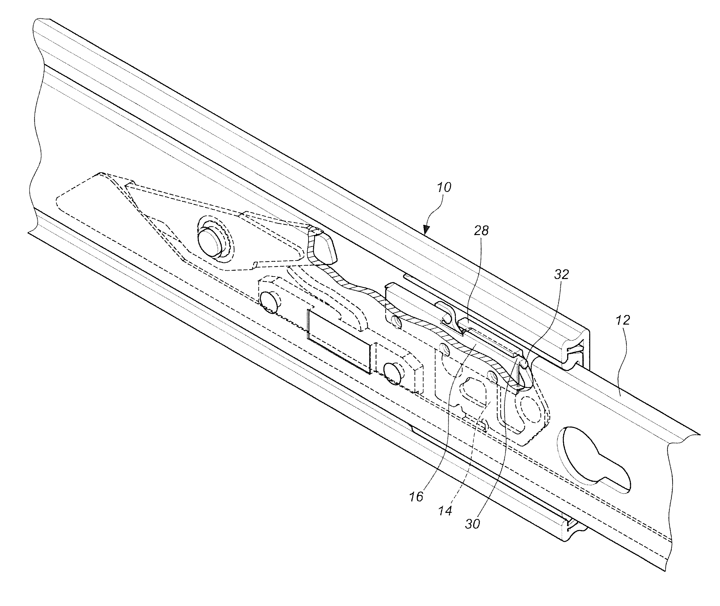
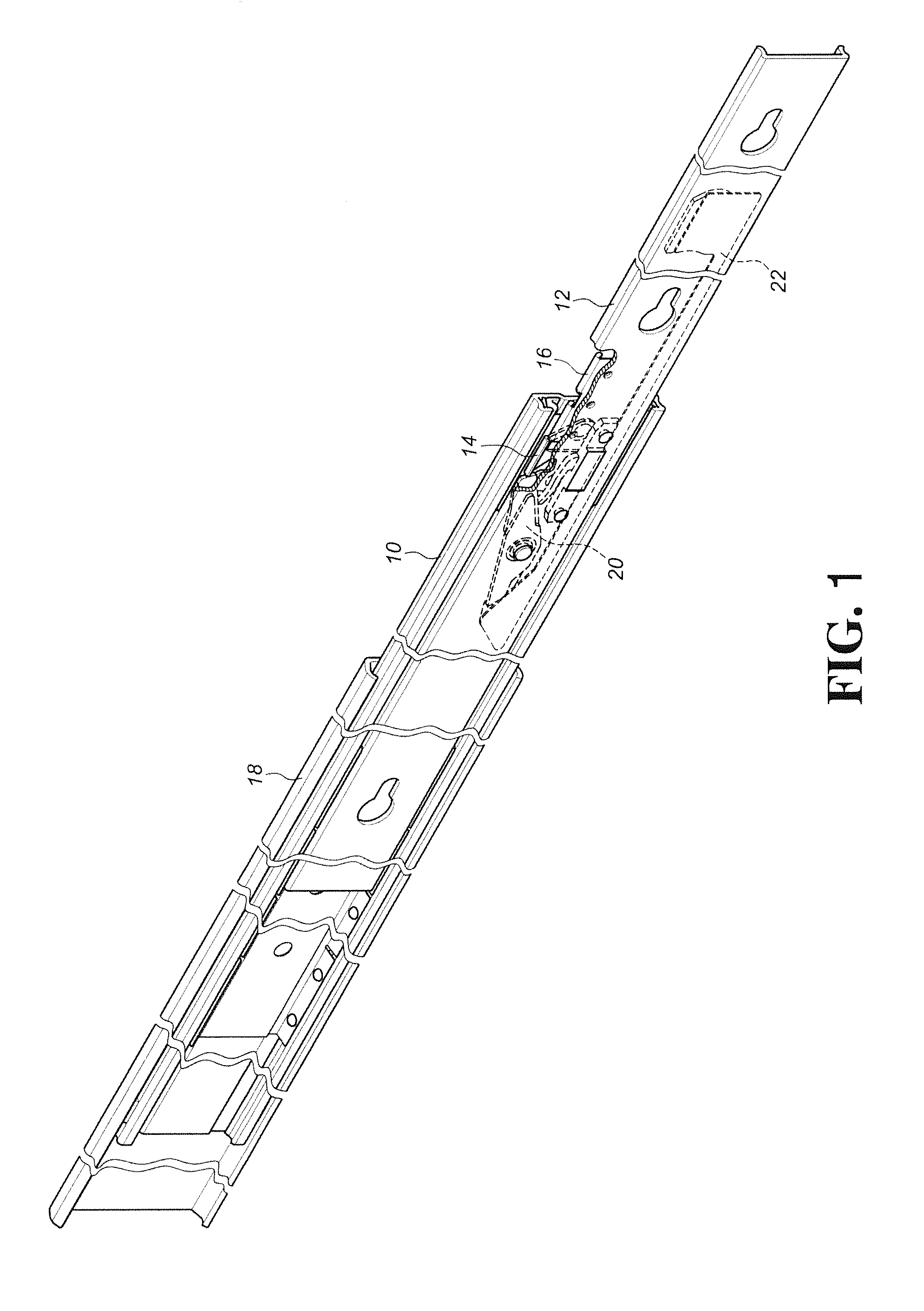
[0018]Referring to FIGS. 1 and 2, the slide assembly of the present invention comprises a first rail 10, a second rail 12, a stop member 14, a friction member 16, a third rail 18, an engaging member 20 and a linkage member 22.

[0019]The first rail 10 comprises two sidewalls 24 and a connection wall 26, wherein the connection wall 26 is connected between the two sidewalls 24.

[0020]The second rail 12 is slidably connected to the first rail 10 and located between the two sidewalls 24.

[0021]The stop member 14 is fixed to the connection wall 26 of the first rail 10 and has a stop plate 28, wherein the stop plate 28 is substantially perpendicular to the connection wall 26 of the first rail 10.

[0022]The friction member 16 is fixed to the second rail 12 and has an extension portion 30 which is located corresponding to the stop plate 28 of the stop member 14 and has two opposite ends. The extension portion 30 has a guide face 32 formed thereon and corresponding to the stop plate 28. Preferabl...


PUM


Abstract

A slide assembly includes a first rail, a second rail, a stop member and a friction member. The first rail includes two sidewalls with a connection wall connected therebetween. The second rail is slidably located between the two sidewalls of the first rail. The stop member is fixed to the connection wall and has a stop plate which is perpendicular to the connection wall. The friction member is fixed to the second rail and has an extension portion. The extension portion has a guide face. When the second rail is moved relative to the first rail after the friction member touches the stop plate and overlaps the stop member by the guide face, the friction member is slidably and flexibly in contact with the stop plate.

Description

FIELD OF THE INVENTION[0001]The present invention relates to a slide assembly, and more particularly, to a slide assembly with a deceleration device used for decelerating the speed of a moving rail of a slide assembly.BACKGROUND OF THE INVENTION[0002]The conventional slide assemblies with positioning devices for positioning rails, disclosed in U.S. Pat. No. 6,412,891 to Liang et al. and U.S. Pat. No. 6,945,619 to Chen et al., are referenced in the present invention. However, these two conventional slide assemblies of the prior art do not have a deceleration device so that when the rails is pulled to a desired position by a significant force, the positioning device generates impact noise, and / or the reliability of the positioning device is decreased.[0003]The present invention intends to provide a slide assembly with a deceleration device used for slowing down the speed of the rail when the rail is pulled / extended to close to its fully extension position.SUMMARY OF THE INVENTION[0004...

Claims


Application Information

Patent Timeline
Patent Type & Authority Patents(United States)
IPC IPC(8): A47B88/08A47B88/00A47B88/49
CPCE05F5/003A47B88/10E05Y2800/122E05Y2201/20E05Y2201/26A47B88/08E05D15/0652E05D15/0686A47B2210/0094A47B88/49A47B88/493
Inventor CHEN, KEN-CHINGYANG, SHUN-HOYEH, CHIH-HSINWENG, CHENG-CHIEHWANG, CHUN-CHIANG
Owner KING SLIDE WORKS CO LTD
Learn More