
Method for the production of a high-pressure accumulator pipe of steel for fuel injection systems and high-pressure accumulator pipe produced according to this method

a technology of accumulator pipe and high-pressure accumulator pipe, which is applied in the direction of rigid pipes, fuel injection apparatus, mechanical equipment, etc., can solve the problems of high cost, high production cost, and inability to meet the demands of surface quality and the properties of marginal drilling zones, so as to reduce production costs, improve residual compressive stress, and improve the effect of fatigue strength of components

Active Publication Date: 2014-12-30
SALZGITTER MANNESMANN PRECISION
View PDF10 Cites 2 Cited by
  • Summary
  • Abstract
  • Description
  • Claims
  • Application Information

AI Technical Summary

Benefits of technology

The invention describes a method for producing high-pressure accumulator pipes from composite pipes that reduces production costs while still meeting the demands on the surface. The method achieves this by reducing surface roughness values to very small levels, which reduces stress concentrations and notch effects that can affect fatigue strength. The method also introduces residual compressive stress onto the inner pipe part, which positively impacts fatigue strength and may eliminate the need for additional smoothing processes or complicated deep drilling processes. This results in an improved fatigue strength of the accumulator pipe while reducing material costs. Additionally, the method allows for the use of various material combinations to suit different demands on the inner and outer pipe parts.

Problems solved by technology

The surface quality and the properties of the marginal drilling zone oftentimes do not meet the demands and the required high fatigue strength can only be realized through an additional autofrettage process.
As cold-finished pipes require two drawing processes, high costs are incurred and the pipes oftentimes exhibit insufficient surface quality and inadequate properties at the marginal zones, and the application of a cost-intensive autofrettage is also necessary.
This is also disadvantageous because the inner pipe part produced by deep drilling.

Method used


Image

  • Method for the production of a high-pressure accumulator pipe of steel for fuel injection systems and high-pressure accumulator pipe produced according to this method
  • Method for the production of a high-pressure accumulator pipe of steel for fuel injection systems and high-pressure accumulator pipe produced according to this method
  • Method for the production of a high-pressure accumulator pipe of steel for fuel injection systems and high-pressure accumulator pipe produced according to this method

Examples


Embodiment Construction

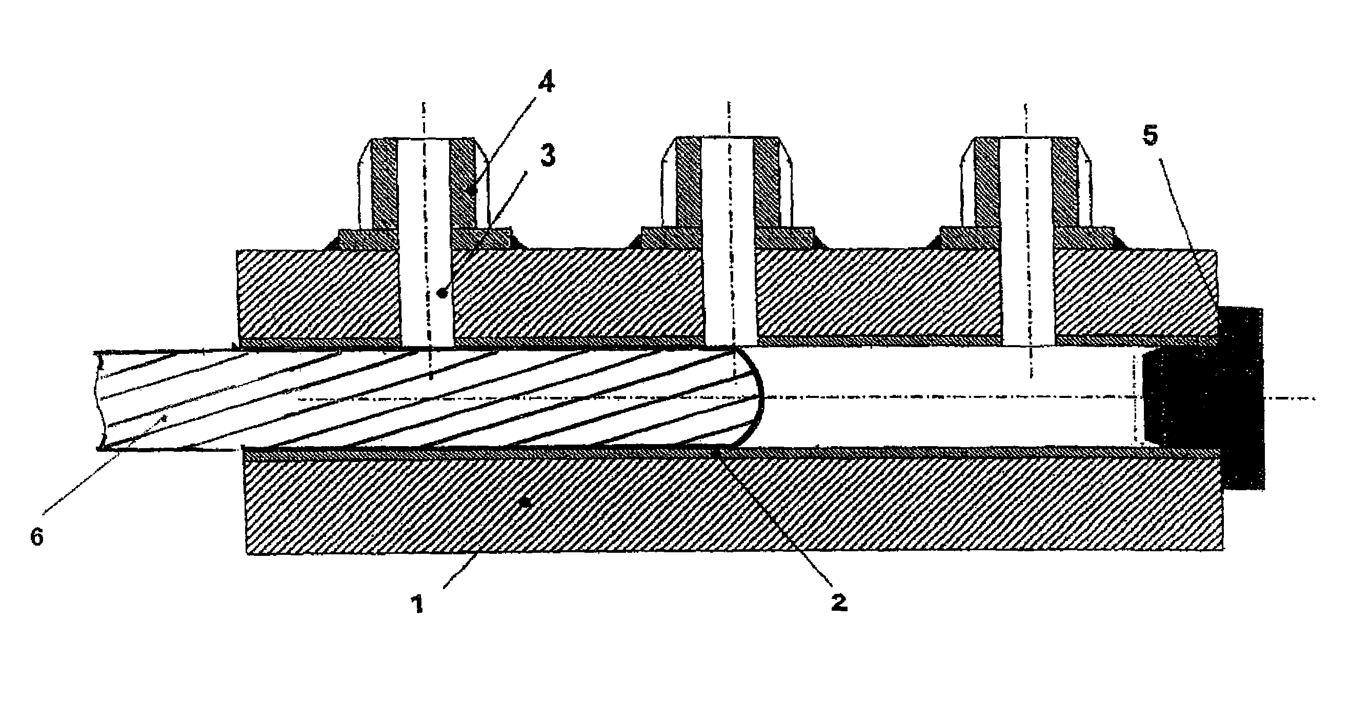
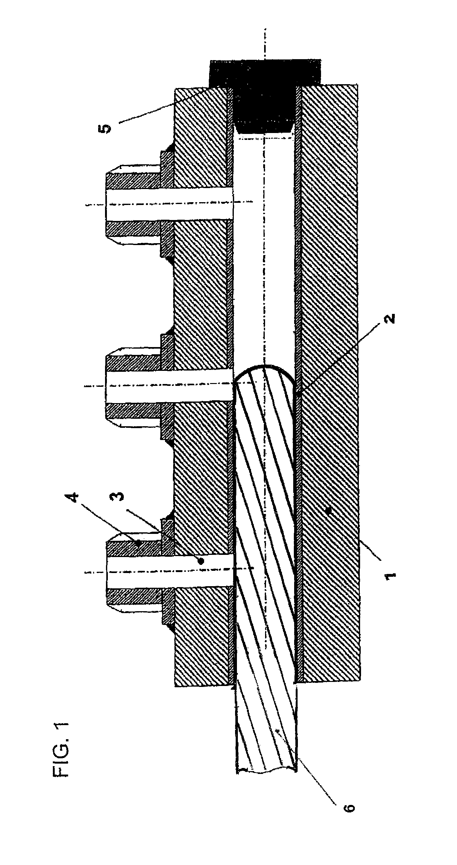
[0032]The high-pressure accumulator pipe constructed as composite pipe includes a first inner pipe part 2 which is inserted in a second outer pipe part 1 with little clearance.

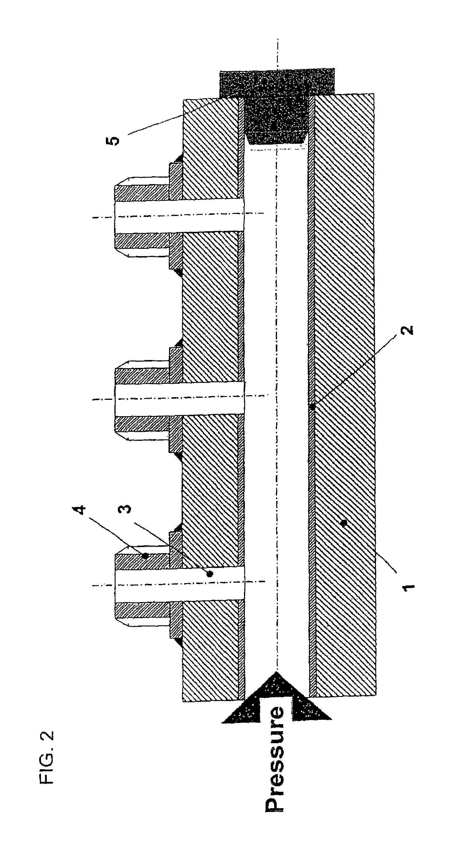
[0033]In accordance with the invention, the composite pipe is produced through rolling-in the pipe using an oversized rolling tool 6 that is moved within the inner pipe part 2, as shown in FIG. 1. After the rolling-in process, as shown in FIG. 2, the inner pipe part 2 is acted upon with a residual compressive stress adjusted to the operating pressure via the elastic resilience of the outer pipe part 1, and the inner surface of the inner pipe part 2 has roughness values of Rz in the range of ≦1.0 μm and a roughness Ra in the range of ≦0.2 μ.

[0034]The outer pipe part 1 is configured relatively thick-walled and is made of an unalloyed or low-allow steel. The inner part 2 is configured relatively thin-walled and made of a high-alloy material which is suited to a plastic deformation during the rolling-in process of...


PUM

PropertyMeasurementUnit
pressuresaaaaaaaaaa
roughness Raaaaaaaaaaa

Abstract

In a method of making a high-pressure accumulator pipe as composite pipe of steel for pressures of up to 1800 bar and above with high static strength and fatigue strength for fuel injection systems with common rail systems for internal combustion engines, a first inner pipe part is inserted into a second outer pipe part with little clearance, and the inner pipe part is connected to the outer pipe part gap-free and by interference fit through mechanical forming. The mechanical forming includes a rolling-in process, wherein the inner pipe part is subjected to a ductile expansion and the outer pipe part is subjected to an elastic expansion using an oversized rolling tool that is moved within the inner pipe part, and wherein a residual compressive stress adjusted to the operating pressure is applied to the inner pipe part after the forming process via the elastic resilience of the outer pipe part.

Description

CROSS-REFERENCES TO RELATED APPLICATIONS[0001]This application is the U.S. National Stage of International Application No. PCT / DE20081000041, filed Jan. 10, 2008, which designated the United States and has been published as International Publication No. WO 2008 / 106911 and which claims the priority of German Patent Application, Serial No. 10 2007 011 868.8, filed Mar. 7, 2007, pursuant to 35 U.S.C. 119(a)-(d).BACKGROUND OF THE INVENTION[0002]The invention relates to a method of making a high-pressure accumulator pipe of steel for fuel injection systems as well as to a high-pressure accumulator pipe.[0003]High-pressure accumulator pipes for fuel injection systems of internal combustion engines are also designated as common rail system. Pressure generation and fuel injection are decoupled from one another in the common rail system.[0004]A separate high-pressure pump produces continuously pressure which is stored in the central high-pressure accumulator independently from the injection ...

Claims


Application Information

Patent Timeline
Patent Type & Authority Patents(United States)
IPC IPC(8): B21K25/00B21D39/06B21C37/15B21D39/00F02M55/02
CPCF02M2200/9053B21D39/06B21C37/154F02M55/025F02M2200/80B21K25/00Y10T29/49927Y10T29/49911
Inventor HAGEDORN, MICHAELLECHTENFELD, UWE
Owner SALZGITTER MANNESMANN PRECISION
Learn More