LDO with improved stability
a voltage regulator and stability technology, applied in the direction of electrical variable regulation, process and machine control, instruments, etc., can solve the problems of complex and thus costly schemes, ldos easily become unstable, and bond wires are used
- Summary
- Abstract
- Description
- Claims
- Application Information
AI Technical Summary
Benefits of technology
Problems solved by technology
Method used
Image
Examples
case 1
[0033] One solution is to place a series resistor between the pass device and the output Vout, artificially increasing the equivalent ESR. However, this fix will impact the drop-out voltage of the LDO and the load-transient behavior. For output load models we have assumed an equivalent ESR of 100 mΩ. With this ESR, a simulation run shows that the LDO has a phase-margin of about 40° at 100 mA output current, Vout=2.4V and Vdd=3V. If this ESR is reduced to the unlikely case of 1 mΩ, then this phase margin falls to about −5°.
[0034]Referring to FIG. 3a, we show a graph of a computer simulation of Case 1 and an ESR of 100 mΩ with Vout=2.4V and Vdd=3V, for an output current of 100 mA as described above. The horizontal axis displays frequency in Hz ranging from 10−1 to 107. The vertical axis displays Y0 in db for output and Y1 in degrees for the phase. Curve 1 shows the magnitude of the output signal Vout, Curve 2 shows the phase. At Vout=0 the phase margin is 31.47° i.e. the circuit is st...
case 2
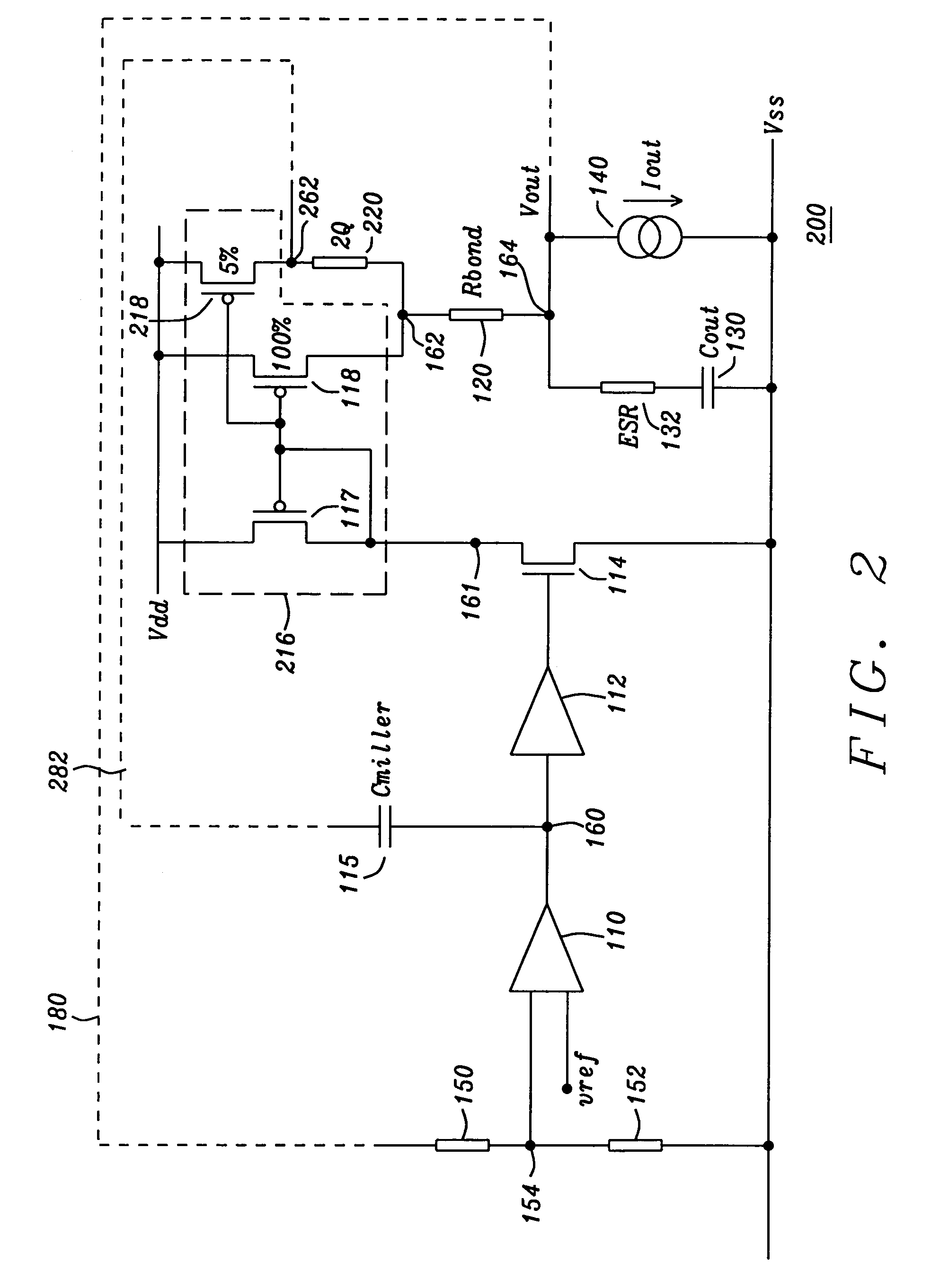
[0036] In the preferred embodiment of the present invention, and referring to FIG. 2, we propose to add another pass device in parallel with the main pass device. A more detailed description of this new circuit follows below. This pass device 218 would be typically about 5% of the existing 100% channel width of the main pass 118 device, but pass device 218 may range from between about 1 to 10% but preferably ranges from between about 0.5 to 15% of the existing channel width of the main pass device. The new pass device will share the power connection and the gate connection. However, between the drain and the output of the LDO is placed a resistor of typically about 2 Ω but which may range from between about 1 to 5 Ω but preferably ranges from between about 0.5 to 10 Ω. The Miller capacitor is now connected to the drain of this new pass device. This means the Miller capacitor sees a much greater ESR, and so it amplifies the fast feedback loop gain, moving the zero node back within th...
PUM
 Abstract
Description
Claims
Application Information
 - R&D
- Intellectual Property
- Life Sciences
- Materials
- Tech Scout
- Unparalleled Data Quality
- Higher Quality Content
- 60% Fewer Hallucinations
Browse by: Latest US Patents, China's latest patents, Technical Efficacy Thesaurus, Application Domain, Technology Topic, Popular Technical Reports.
© 2025 PatSnap. All rights reserved.Legal|Privacy policy|Modern Slavery Act Transparency Statement|Sitemap|About US| Contact US: help@patsnap.com


