
Diesel injector and method utilizing focused supercavitation to reduce spray penetration length

a diesel engine and supercavitation technology, applied in the direction of spray nozzles, mechanical equipment, machines/engines, etc., can solve the problems of long fuel jet penetration length, limited progress to larger engines in the output power range of 40 hp, and technical limitations, so as to avoid excessive momentum flux, shorten the penetration length, and quick fuel delivery

Active Publication Date: 2014-12-09
MAINSTREAM ENG
View PDF12 Cites 11 Cited by
  • Summary
  • Abstract
  • Description
  • Claims
  • Application Information

AI Technical Summary

Benefits of technology

The patent describes a new type of cavitation, called supercavitation, which improves fuel spray penetration and reduces the need for larger fuel injectors in engines. By using a special flow path, the cavitation occurs at the minimum pressure upstream of the nozzle, resulting in quick fuel delivery and effective atomization without excessive force. This approach also reduces erosion and fuel-related issues in the engine. Overall, the patent provides a method for improved fuel injection using supercavitation.

Problems solved by technology

These advances have been primarily limited to larger engines in the output power range of 40 hp or greater.
This has been due to inherent technical limitations with scaling to smaller engines.
The conventional approach has been to enhance these features by using high fuel pressures (up to 2,500 bar) but this has been found to result in long fuel jet penetration lengths, something which is not desirable for a small engine injection system.
Long fuel jet penetration lengths in small engine piston bowls / cylinders lead to wetting the piston bowl wall and cylinder wall which can reduce fuel vaporization rates, increase emissions, increase ignition delay, and wash lubricants from the cylinder wall decreasing durability / performance.
The prior art recognizes that to provide a high-pressure injector for small engines much less than 40 hp range requires that the fuel spray penetration length be significantly decreased but up until now has not found any practical way of doing so.
Other phenomenon that impact the design of the proposed supercavitating nozzle is that once supercavitation occurs, the mass flux through a given orifice is choked.

Method used


Image

  • Diesel injector and method utilizing focused supercavitation to reduce spray penetration length
  • Diesel injector and method utilizing focused supercavitation to reduce spray penetration length
  • Diesel injector and method utilizing focused supercavitation to reduce spray penetration length

Examples


Embodiment Construction

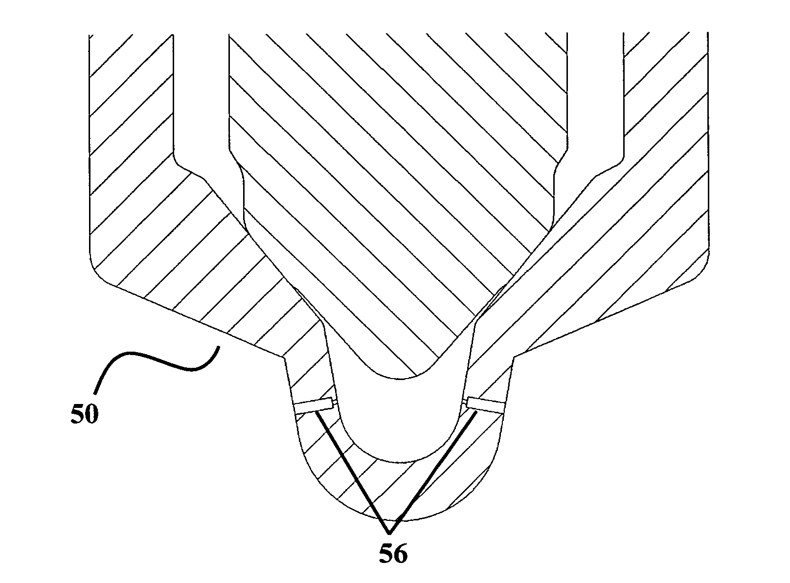
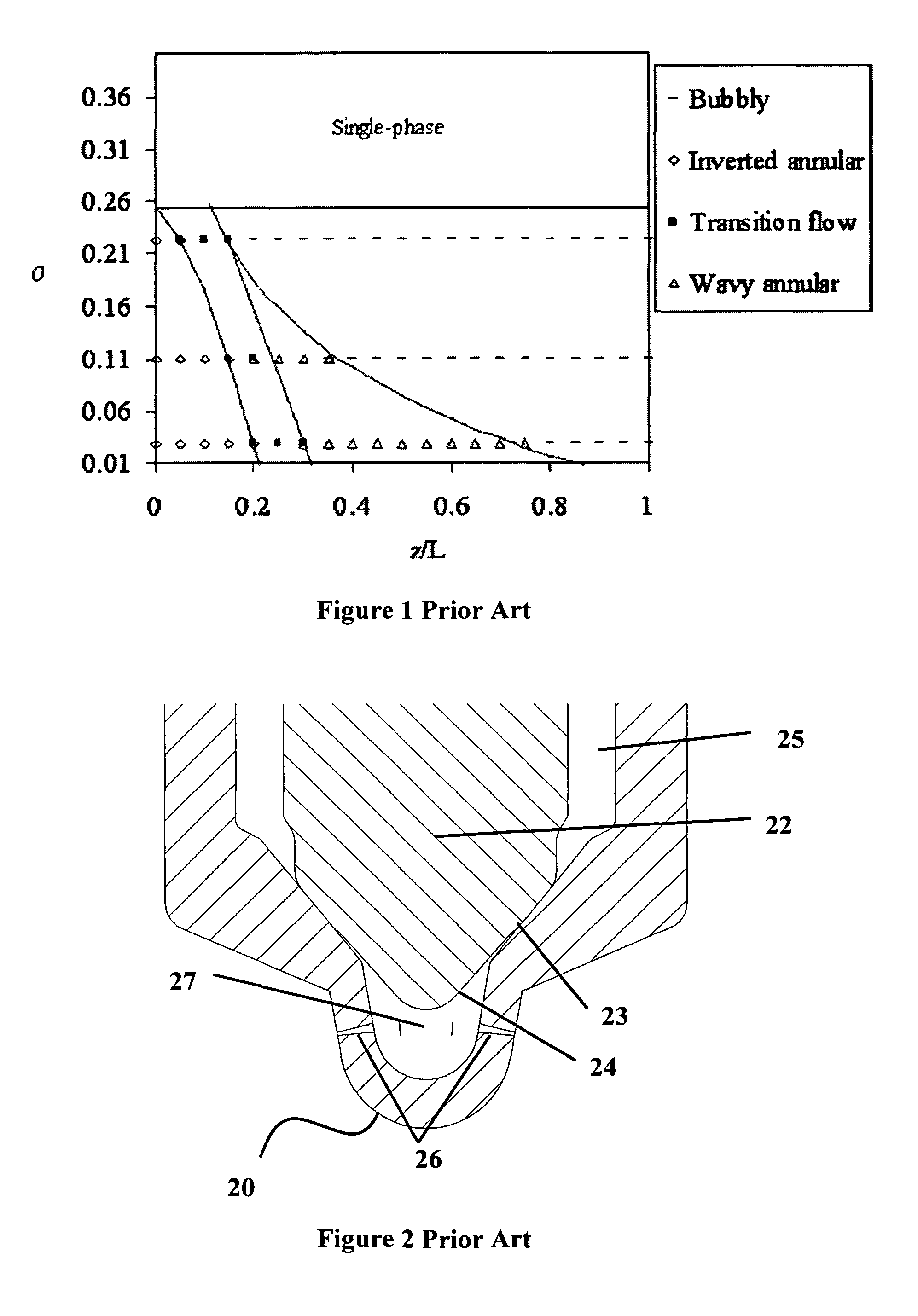
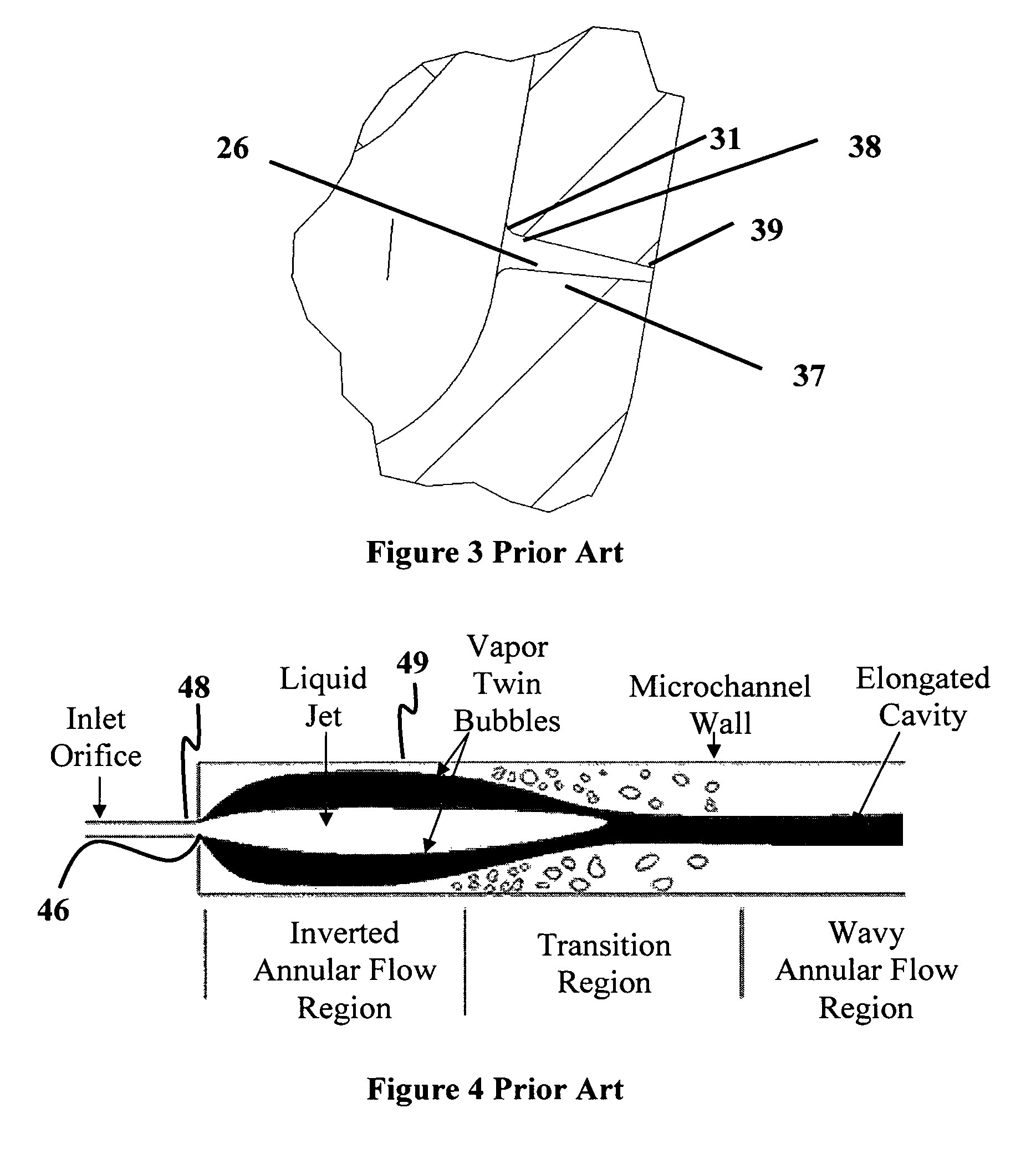
[0027]A supercavitating injector according to the present invention has the advantage that it can be incorporated onto existing piezo-electric or solenoid type, modern diesel fuel injectors. The conventional injector has a plurality of rounded and tapered nozzles that emanate from a sac volume as shown in FIG. 2. High pressure fuel is fed from a pump to fill a large portion of the injector. A moveable needle segregates this internal portion of the injector to a sac volume. The sac volume typically has either one or a plurality of nozzles that are in fluidic communication with the sac volume and are responsible for delivering fuel to the combustion cylinder of the engine.

[0028]More specifically, FIG. 2 shows a conventional injector tip (20) that is typically used currently in the diesel engine field in which a moveable needle (22) creates a mechanical seal (23) with the injector tip (24) while not in operation. During this time, full fluid pressure exists above this seal, and a sac v...


PUM


Abstract

A method and apparatus are disclosed for inducing a supercavitating flow inside a fuel injection nozzle orifice to reduce the penetration length of the fuel spray, maintain high levels of fuel atomization, and improve uniformity of the fuel spray exiting the nozzle such that high-pressure injectors can be used on small engines. This reduction in penetration length is accomplished without any reduction in upstream fuel pressure.

Description

BACKGROUND AND SUMMARY OF THE INVENTION[0001]The present invention relates to a method and apparatus for reducing spray penetration length for diesel engines, and more particularly to a method and apparatus that uses supercavitation so as to allow highly atomized sprays to be employed for small engine, high-pressure diesel injection systems.[0002]Over the past two decades, advances in high-pressure, electronically-controlled diesel fuel injection technology have had a significant impact on diesel engine efficiency, exhaust emissions, and engine noise. These advances have been primarily limited to larger engines in the output power range of 40 hp or greater. This has been due to inherent technical limitations with scaling to smaller engines. Along with the development of electronically controlled fuel injection, researchers and manufacturers have made use of increasing fuel pressures as a method to produce highly atomized sprays and deliver fuel to the cylinder quickly. Highly atomiz...

Claims


Application Information

Patent Timeline
Patent Type & Authority Patents(United States)
IPC IPC(8): F02M61/00
CPCF02M61/1833F02M61/1806F02M61/00
Inventor SYKES, DAVID M.HOMITZ, JOSEPHCOLE, GREGORY S.
Owner MAINSTREAM ENG
Learn More