
Diesel injector capable of successively injecting oil

A diesel engine and fuel injector technology, applied in the direction of machines/engines, mechanical equipment, engine components, etc., can solve the problems that the installation position of the fuel injector cannot be guaranteed, high cost, and the strength of the cylinder head is reduced, so as to improve fuel atomization Performance, efficiency improvement, effect of reducing soot and HC emissions

Inactive Publication Date: 2014-03-05
HARBIN ENG UNIV
View PDF6 Cites 6 Cited by
  • Summary
  • Abstract
  • Description
  • Claims
  • Application Information

AI Technical Summary

Problems solved by technology

But the cost is high, and the installation position of the fuel injector cannot be guaranteed, which will also reduce the strength of the cylinder head

Method used


Image

  • Diesel injector capable of successively injecting oil
  • Diesel injector capable of successively injecting oil
  • Diesel injector capable of successively injecting oil

Examples


Embodiment Construction

[0012] The present invention is described in more detail below in conjunction with accompanying drawing example:

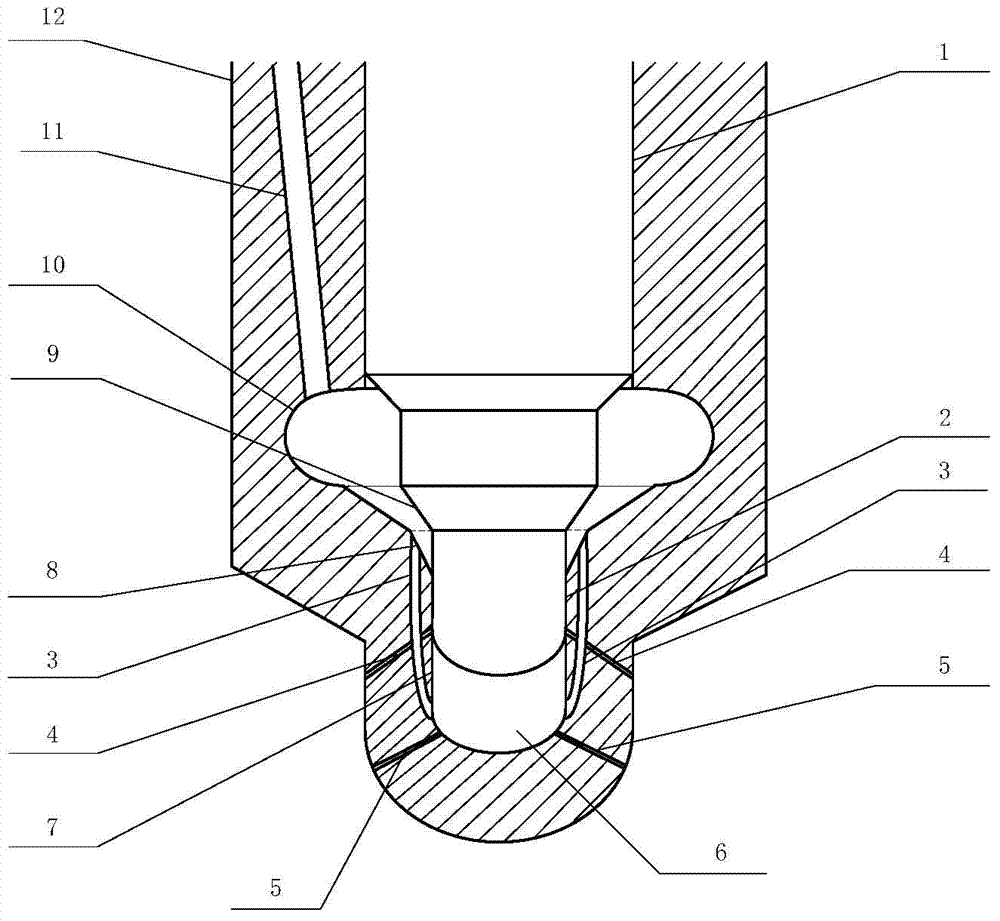
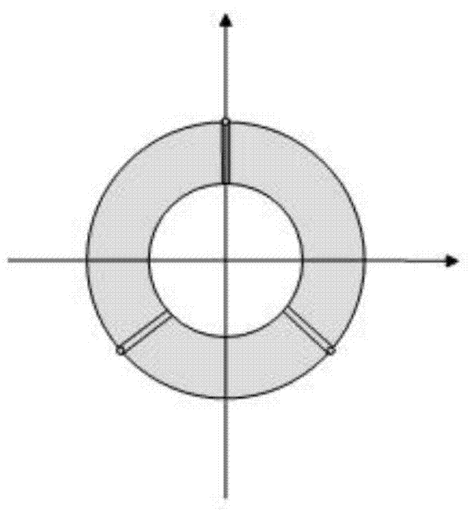
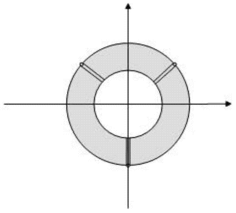
[0013] combine Figure 1~3 , the needle valve body 1 of the present invention follows the form of the traditional fuel injector, and the main innovations are the improvement of the bottom of the needle valve, the design of the fuel injection hole, and the design of the channel 3 to realize the change of the input fuel injection according to the fuel injection volume. A function of the number of orifices. by figure 1 Shown to illustrate the positional relationship of the main components of the present invention:

[0014] The needle valve cone surface 9 is in the shape of a conical surface at the bottom of the needle valve body 1, and when the needle valve body 1 is seated, it is precisely matched with the needle valve sealing surface 8 below; The upper and lower ends of the sealing surface 8 are opened at the bottom of the injection chamber 6; the sealing piston...


PUM


Abstract

The invention aims to provide a diesel injector capable of successively injecting oil. The diesel injector comprises an outer shell and a needle valve body. The needle valve body is located in the outer shell. The outer shell is provided with an oil inlet groove and a needle valve cavity. The oil inlet groove is communicated with the needle valve cavity. The needle valve body comprises a sealing piston and a needle valve conical surface, wherein the sealing piston is arranged on the end portion of the needle valve body, and the needle valve conical surface is located above the sealing piston. The inner wall of the outer shell is provided with a needle valve sealing surface which is located below the needle valve cavity. An oil injection cavity is formed between the sealing piston and the bottom end of the inner wall of the outer shell. The needle valve cavity is communicated with the oil injection cavity through passages. The upper ends of the passages are located in the needle valve sealing surface. When the needle valve body drops in place, the needle valve conical surface is matched with the needle valve sealing surface to enable the passages to be disconnected with the needle valve cavity. A first layer of spray orifices and a second layer of spray orifices are formed in the bottom end of the outer shell respectively. The first layer of spray orifices is located below the second layer of spray orifices. Through the diesel injector capable of successively injecting the oil, the fuel oil atomization performance at low load, the fuel oil wall-wetting phenomenon at high load and fuel oil distribution uniformity in the air are improved, so efficiency is improved, and soot emission and HC emission are reduced.

Description

technical field [0001] The invention relates to a diesel engine, specifically a fuel injector for a diesel engine. Background technique [0002] The fuel injectors used in existing diesel engines can basically guarantee better atomization at medium and high loads, because the fuel injection pressure is higher at medium and high loads, and the designed nozzle size of the fuel injector can ensure better atomization effect. But at low load, if the original nozzle hole is still used, due to the small amount of fuel injection, if the high-pressure common rail fuel injection system is not used, the fuel injection pressure is also low at this time, and a better atomization effect cannot be guaranteed; If a high-pressure common rail fuel injection system is adopted, the fuel atomization effect can be further improved due to the less fuel injection. For diesel engines, how to improve fuel atomization under low operating conditions has always been a difficult problem for everyone. A...

Claims


Application Information

Patent Timeline
Patent Type & Authority Applications(China)
IPC IPC(8): F02M61/10F02M61/18
Inventor 王银燕胡松王玥王贺春杨传雷祖象欢崔欣洁牛晓晓
Owner HARBIN ENG UNIV
Learn More