
Shock absorbing device for vehicle with multiple shock absorbing stages

a technology of shock absorption device and vehicle, which is applied in the direction of shock absorbers, elastic dampers, bumpers, etc., can solve the problems of vehicle accident, low energy absorption capacity per unit mass of a member, and heavy apparatus weight, etc., to increase collision energy absorption performance, high strength, and high elongation material characteristics

Active Publication Date: 2014-11-25
POHANG IRON & STEEL CO LTD
View PDF18 Cites 4 Cited by
  • Summary
  • Abstract
  • Description
  • Claims
  • Application Information

AI Technical Summary

Benefits of technology

[0013]An aspect of the present invention provides a collision energy absorbing apparatus for use in a vehicle, having a plurality of absorption phases. The collision energy absorbing apparatus according to an aspect of the present invention may be provided to increase collision energy absorption performance per unit length by using high strength and high elongation material characteristics. In the collision energy absorbing apparatus according to an aspect of the present invention, collision energy may be effectively absorbed even in the case that the length of a space required to absorb collision energy is relatively short, collision energy generated at the time of a vehicle crash may be absorbed in phases, and relatively high amount of collision energy may also be absorbed, and thus, the production of a light-weight vehicle may be possible. In addition, absorption of collision energy appropriate to respective low speed and high speed collisions may be applied, and a collision acceleration may be significantly reduced such that passenger injuries may be reduced. Further, a collision crush space may be reduced so as to decrease limitations in the design of a vehicle.

Problems solved by technology

In a vehicle such as a car, a train, or the like, moving at a high speed, a vehicle accident may occur due to a collision with another vehicle or a fixed structure.
However, since bending deformation may occur in a material and thus sufficient plastic deformation may not be provided therein, the energy absorption capability per unit mass of a member may be relatively low.
However, in this method, since a portion thereof, provided to expand a tube is a rigid body and so is not deformed, the weight of the apparatus may be heavy.
This is the current situation with regard to difficulties in configuring an apparatus for wholly absorbing collision energy by using only plastic deformation utilizing tube-expansion.
In this case, since the collision energy absorption method using the existing crush method has a small amount of plastic deformation from bending deformation, it is inappropriate to sufficiently utilize the high energy absorption capabilities of a high-elongation material and thus, a relatively large crush space is required.
Thus, plastic deformation may be generated intensively only on a folded portion of the plate.
Therefore, in terms of an overall collision member, the amount of plastic deformation may not be sufficient for the characteristics of a highly-elongated material.

Method used


Image

  • Shock absorbing device for vehicle with multiple shock absorbing stages
  • Shock absorbing device for vehicle with multiple shock absorbing stages
  • Shock absorbing device for vehicle with multiple shock absorbing stages

Examples


Embodiment Construction

[0037]Embodiments of the present invention will now be described in detail with reference to the accompanying drawings such that they could be easily practiced by those having skill in the art to which the present invention pertains. However, in describing the embodiments of the present invention, detailed descriptions of well-known functions or constructions will be omitted so as not to obscure the description of the present invention with unnecessary detail.

[0038]In addition, like reference numerals denote like elements throughout the drawings.

[0039]Unless explicitly described to the contrary, the word “comprise” and variations such as “comprises” or “comprising,” will be understood to imply the inclusion of stated elements but not the exclusion of other elements.

[0040]According to embodiments of the present invention, a collision energy absorbing apparatus for use in a vehicle having a plurality of absorption phases will be described in detail below.

[0041]Embodiments of the prese...


PUM


Abstract

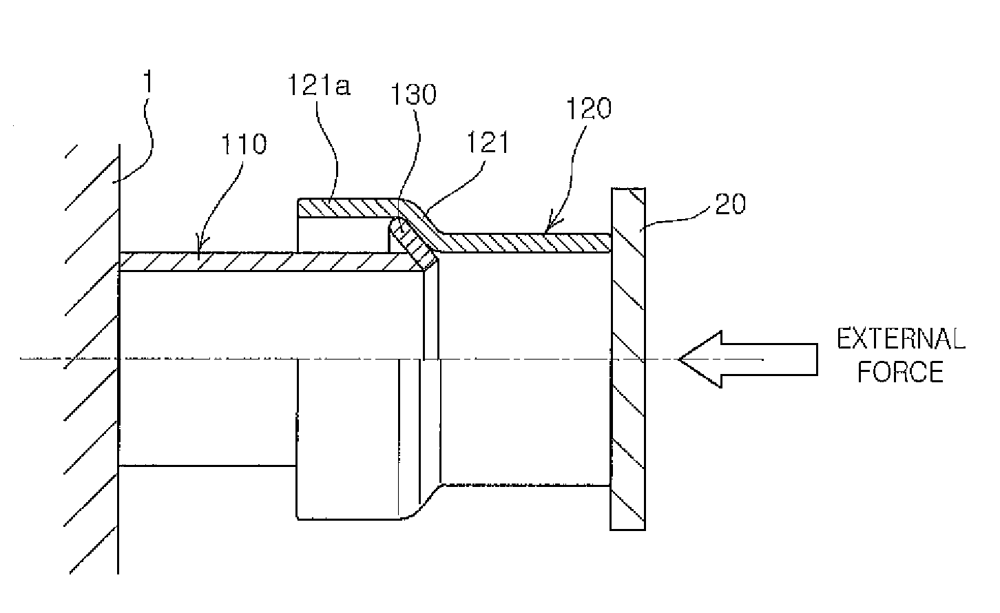
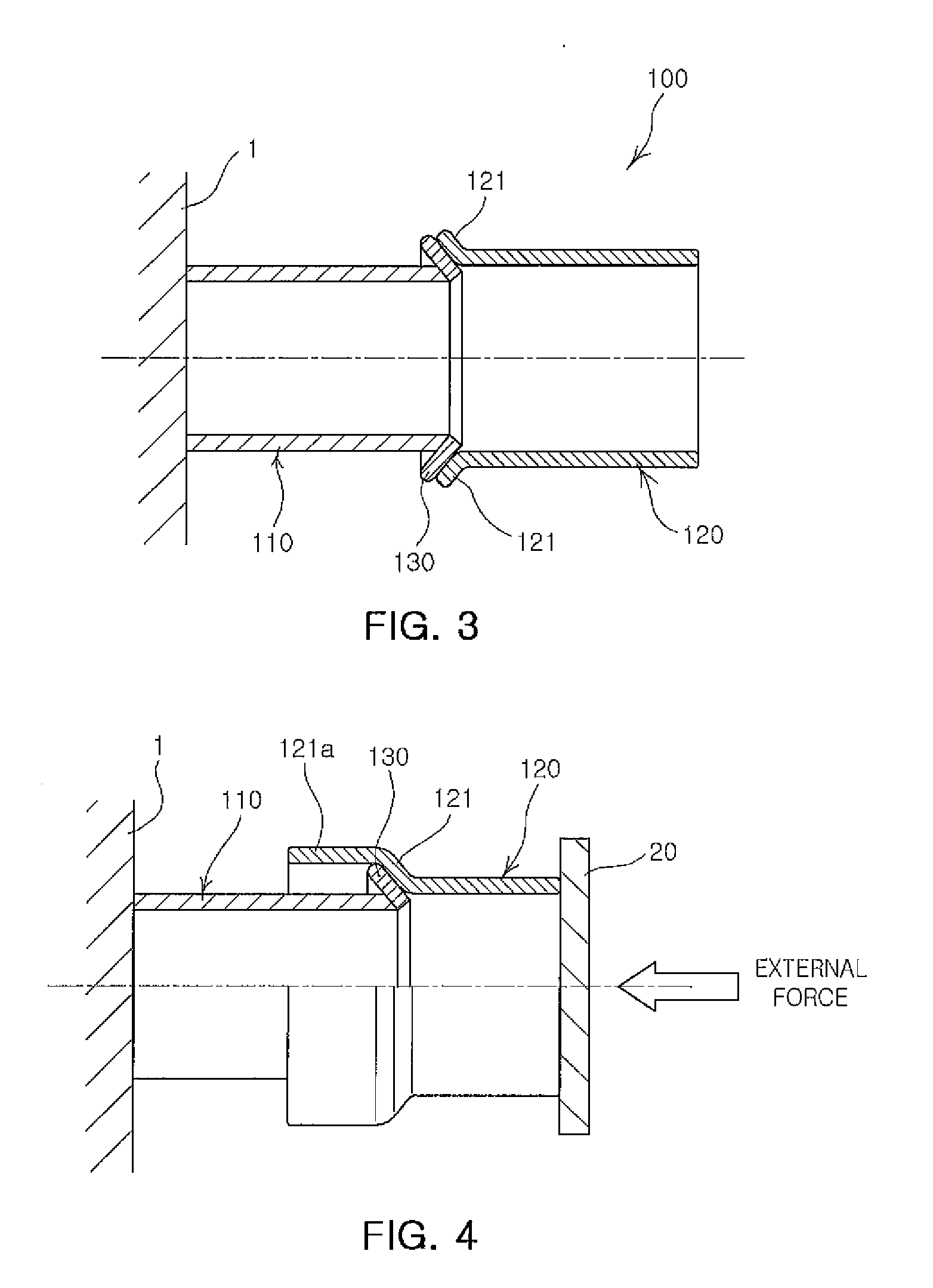
There is provided a collision energy absorbing apparatus, in particular, a collision energy absorbing apparatus for use in a vehicle, having a plurality of absorption phases, including: a first deformation part undergoing a first plastic deformation due to expansion so as to absorb collision energy generated in the event of a vehicle accident; a second transformation part disposed in line with an end of the first deformation part, the second transformation part undergoing a second plastic deformation after the first plastic deformation of the first deformation part so as to sequentially absorb collision energy in the event of a vehicle accident; and an expansion inducing part combined with an end of the second deformation part and disposed between the first deformation part and the second deformation part to guide the first plastic deformation of the first deformation part.

Description

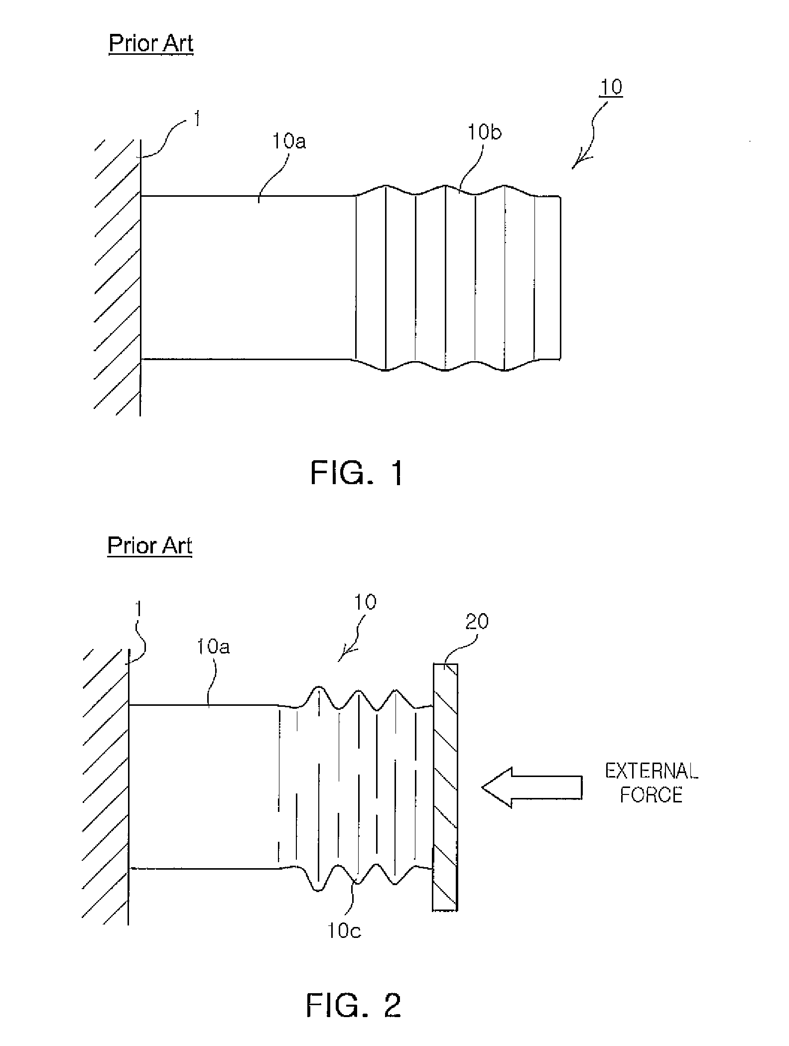
TECHNICAL FIELD[0001]The present invention relates to a collision energy absorbing apparatus for use in a vehicle for protecting passengers from a collision force in the event of a crash or accident.BACKGROUND ART[0002]In general, a vehicle is equipped with a collision energy absorbing apparatus for absorbing shock force to protect passengers in the event of a car accident, for example, a crash.[0003]In a vehicle such as a car, a train, or the like, moving at a high speed, a vehicle accident may occur due to a collision with another vehicle or a fixed structure. In this case, energy generated in the event of a vehicle accident needs to be effectively absorbed in order to secure passenger safety.[0004]A method of absorbing collision energy according to the related art utilizes plastic energy generated when a collision structure member is deformed in the event of an accident. For example, a collision energy absorbing apparatus 10 may include a support part 10a provided with a fixture ...

Claims


Application Information

Patent Timeline
Patent Type & Authority Patents(United States)
IPC IPC(8): B61G11/16B60R19/34B60R19/26F16F7/12
CPCB61G11/16B60R19/34B60R2019/262F16F7/125B60R19/02
Inventor LIM, JI-HO
Owner POHANG IRON & STEEL CO LTD
Learn More