
Method and apparatus for dealing with faults in an electrical drive system

a technology of electrical drive system and fault, applied in the direction of power supply testing, instruments, electric devices, etc., can solve the problem of further massive damage to the electrical drive system

Active Publication Date: 2014-11-04
ROBERT BOSCH GMBH
View PDF13 Cites 4 Cited by
  • Summary
  • Abstract
  • Description
  • Claims
  • Application Information

AI Technical Summary

Benefits of technology

The present invention provides a method for dealing with faults in an electrical drive system having an electrical machine and a pulse-controlled inverter. The method involves detecting a fault in the system, selecting a circuit state of the inverter based on the detected fault, and driving the inverter to set the selected circuit state. This allows for flexible selection of different disconnection states of the electrical machine without risking further damage to the system. The method also allows for reacting to faults or defects in switching devices in the inverter and selecting a safe circuit state. The invention further provides a mechanism for compensating for switching delays in the inverter and reducing high current flows which could otherwise occur during power connection and disconnection processes.

Problems solved by technology

However, fault patterns in the case of which a short circuit to low potential does not represent a safe disconnection state of the electrical drive system or of the electrical machine, for example in the case of low-impedance defects in high-side switches in the pulse-controlled inverter, can occur in electrical drive systems.
In such cases, a short circuit state to low potential would cause a short circuit of the supply voltage of the pulse-controlled inverter, and this can lead to further massive damage to the electrical drive system.

Method used


Image

  • Method and apparatus for dealing with faults in an electrical drive system
  • Method and apparatus for dealing with faults in an electrical drive system

Examples


Embodiment Construction

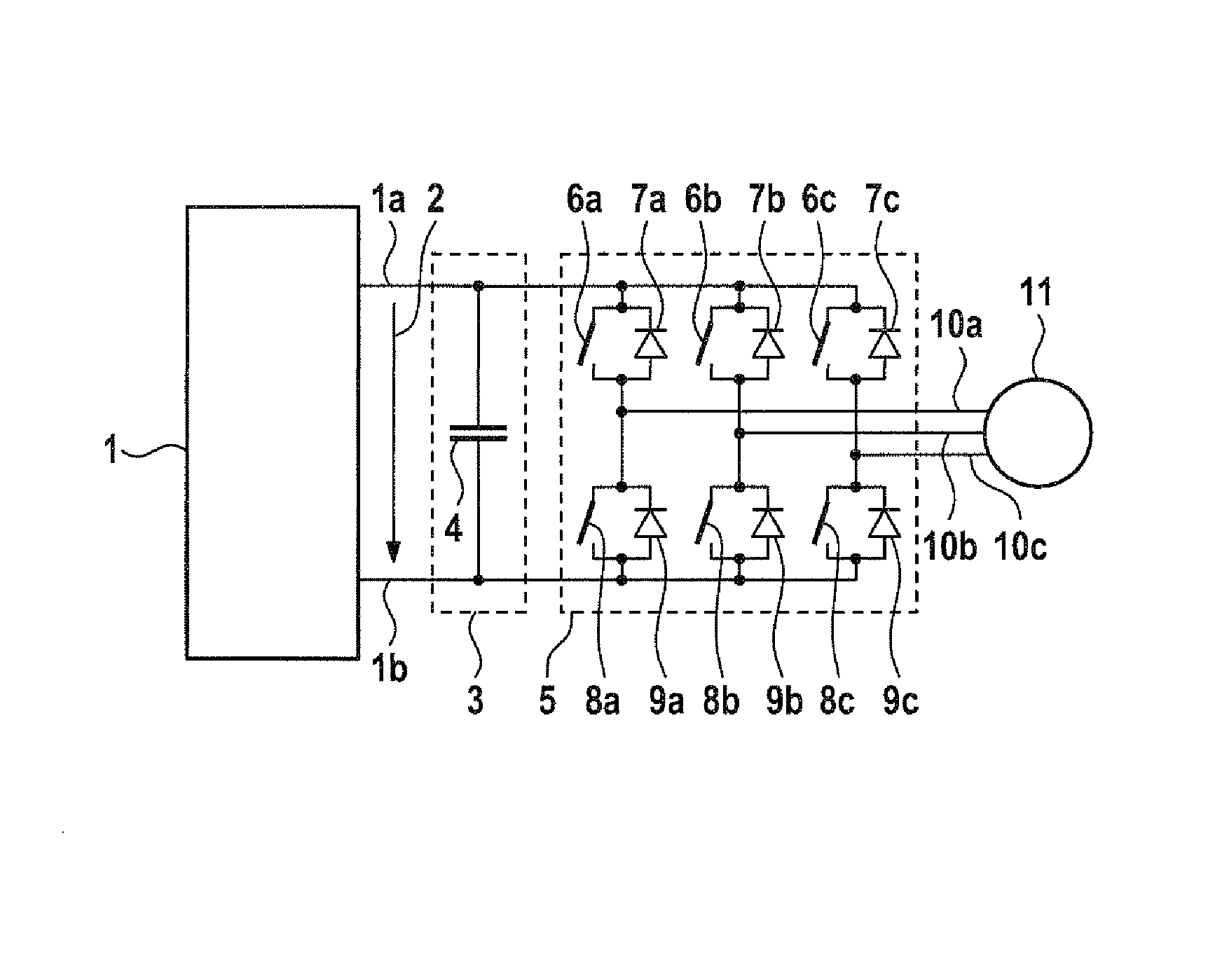
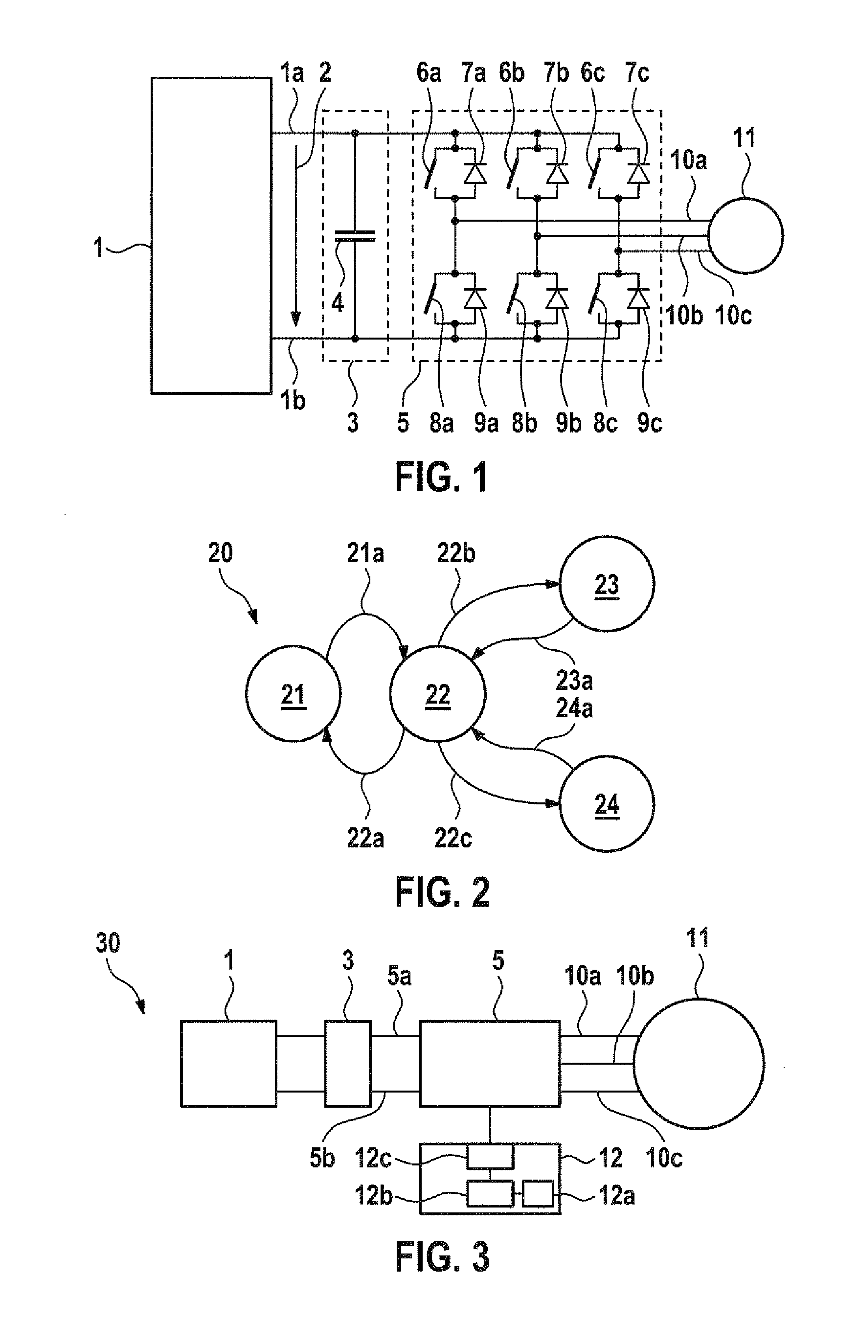
[0021]FIG. 1 shows a schematic illustration of an electrical drive system. The electrical drive system comprises an energy source 1, for example a high-voltage source such as a fraction battery, which can provide a supply voltage 2. The energy source 1 can be designed, for example, as an energy storage means 1 in a drive system of an electrically operated vehicle. It is also possible for the energy source 1 to be system-based, that is to say for the electrical drive system to draw electrical energy from an energy supply system. The supply voltage 2 can be applied to supply connections of a pulse-controlled inverter 5 via an intermediate circuit 3 having an intermediate circuit capacitor 4. In this case, a connection 1a of the energy source 1 is at high potential, and a connection 1b of the energy source 1 is at low potential, for example earth. The pulse-controlled inverter 5 can have, for example, a three-phase output, with a three-phase electrical machine 11 being connected to the...


PUM


Abstract

A method for dealing with faults in an electrical drive system having an electrical machine and a pulse-controlled inverter which has a first and a second supply connection, the method including the steps of: detecting a first fault in the electrical drive system; selecting a first of a large number of circuit states (22, 23, 24) of the pulse-controlled inverter according to the detected first fault; and driving the pulse-controlled inverter to set the first circuit state (23), with the circuit states (22, 23, 24) including a short circuit (23) between the power connections of the electrical machine and the first supply connection, a short circuit (24) between the power connections of the electrical machine and the second power connection, and a free-running mode (22).

Description

BACKGROUND OF THE INVENTION[0001]The invention relates to a method for dealing with faults in an electrical drive system having an electrical machine and a pulse-controlled inverter, to an apparatus for driving a pulse-controlled inverter, and to an electrical drive system having an electrical machine and a pulse-controlled inverter.[0002]Electrical machines having pulse-controlled inverters are used, for example, in hybrid vehicles, where they are operated selectively in motor or generator mode. In motor mode, the electrical machine generates an additional drive torque which assists the internal combustion engine, for example in an acceleration phase, and, in generator mode, said electrical machine generates electrical energy which is stored in an energy storage means, for example a battery or a supercap. The mode of operation and the power of the electrical machine are set by means of the pulse-controlled inverter.[0003]Known pulse-controlled inverters comprise a series of switche...

Claims


Application Information

Patent Timeline
Patent Type & Authority Patents(United States)
IPC IPC(8): G01R31/00B60L3/04B60L3/00G01R31/42
CPCG01R31/42B60L3/04B60L3/003B60L3/0069
Inventor BRUCKHAUS, TIM
Owner ROBERT BOSCH GMBH
Learn More