Eureka AIR delivers breakthrough ideas for toughest innovation challenges, trusted by R&D personnel around the world.

Golf club head and golf club

a golf club and head technology, applied in golf clubs, golf, sport apparatus, etc., can solve the problems of complicated sole shape, hole may complicate the sole shape, and complicated sole shape, etc., and achieve good head stability at the address and high degree of freedom in design of the sol

Active Publication Date: 2014-11-04
SUMITOMO RUBBER IND LTD
View PDF3 Cites 2 Cited by
  • Summary
  • Abstract
  • Description
  • Claims
  • Application Information

AI Technical Summary

Benefits of technology

[0009]It is considered to simplify the shape of the sole in order to enhance the stability of the head at address. However, in this case, a degree of freedom in design of the shape of the sole is reduced.
[0010]It is an object of the present invention to provide a golf club having a high degree of freedom in design of the shape of the sole and excellent head stability at address.
[0018]A golf club having good head stability at address and a high degree of freedom in design of a sole can be obtained.

Problems solved by technology

For example, when a weight is attached to the sole, the shape of the sole may be complicated.
When the weight is removable, the shape of the sole tends to be further complicated.
The hole may complicate the shape of the sole.
As a result of considering reduction in ground resistance, the shape of the sole may be complicated.
The shape of the sole may be complicated also for the reason of design.
On the other hand, the shape of the sole may change the stability of the head at address.
It is hard to address a club in which the direction of the face is not stabilized.
However, in this case, a degree of freedom in design of the shape of the sole is reduced.

Method used


Image

  • Golf club head and golf club
  • Golf club head and golf club
  • Golf club head and golf club

Examples


example 1

[0133]A head body and a face member were welded to obtain a wood type head shown in FIG. 8. The material of the head body was Ti-6Al-4V. A method for manufacturing the head body was a lost-wax precision casting. The material of the face member was Ti-6Al-4V. The face member was obtained by subjecting a rolling plate of Ti-6Al-4V to press processing. The head was a 5-wood. A shaft and a grip were attached to the head to obtain a golf club having a length of 42 inches. The sole surface of the head was made the same as that of the head 40 shown in FIG. 8.

[0134]The face-back directional cross-section of a section A8 except for a portion of a recess was a straight line. On the other hand, the toe-heel directional cross-section of the section A8 was a curved line as a whole protruding to the outer side except for the portion of the recess.

[0135]In example 1, a recess having a weight port existed in a section A2. However, in this example 1, the angle θ (two-section contact lie angle θ) exi...

example 2

[0136]A golf club according to example 2 was obtained in the same manner as in example 1 except that a recess was added to a section A5.

[0137]In example 2, a recess having a weight port existed in a section A2. Furthermore, a recess existed in a section A5. However, in this example 2, the angle θ (two-section contact lie angle θ) existed so that a straight line belonging to a section A1 and a straight line belonging to the section A2 were brought into contact with the ground plane. The range of the angle θ was the same as that of example 1.

example 3

[0142]The whole section A5 in comparative example 1 was the recess. A golf club of example 3 was obtained in the same manner as in comparative example 1 except for above.

[0143]In example 3, a section A1 and a section A2 could be simultaneously grounded by the recess of the section A5. That is, in this example 2, the angle θ (two-section contact lie angle θ) existed so that a point belonging to the section A1 and a point belonging to the section A2 were brought into contact with the ground plane. The range of the angle θ was the same as that of example 1.

[0144]The easiness of addressing for these examples and comparative examples was evaluated.

[Evaluation]

[0145]Ten average golf players used each club to evaluate the easiness of addressing. Of the ten golf players, the number of the golf players estimated that it is easy to address the club of example 1 was 7 players; the number of example 2 was 7 players, the number of example 3 was 6 players, the number of comparative example 1 was ...


PUM


Abstract

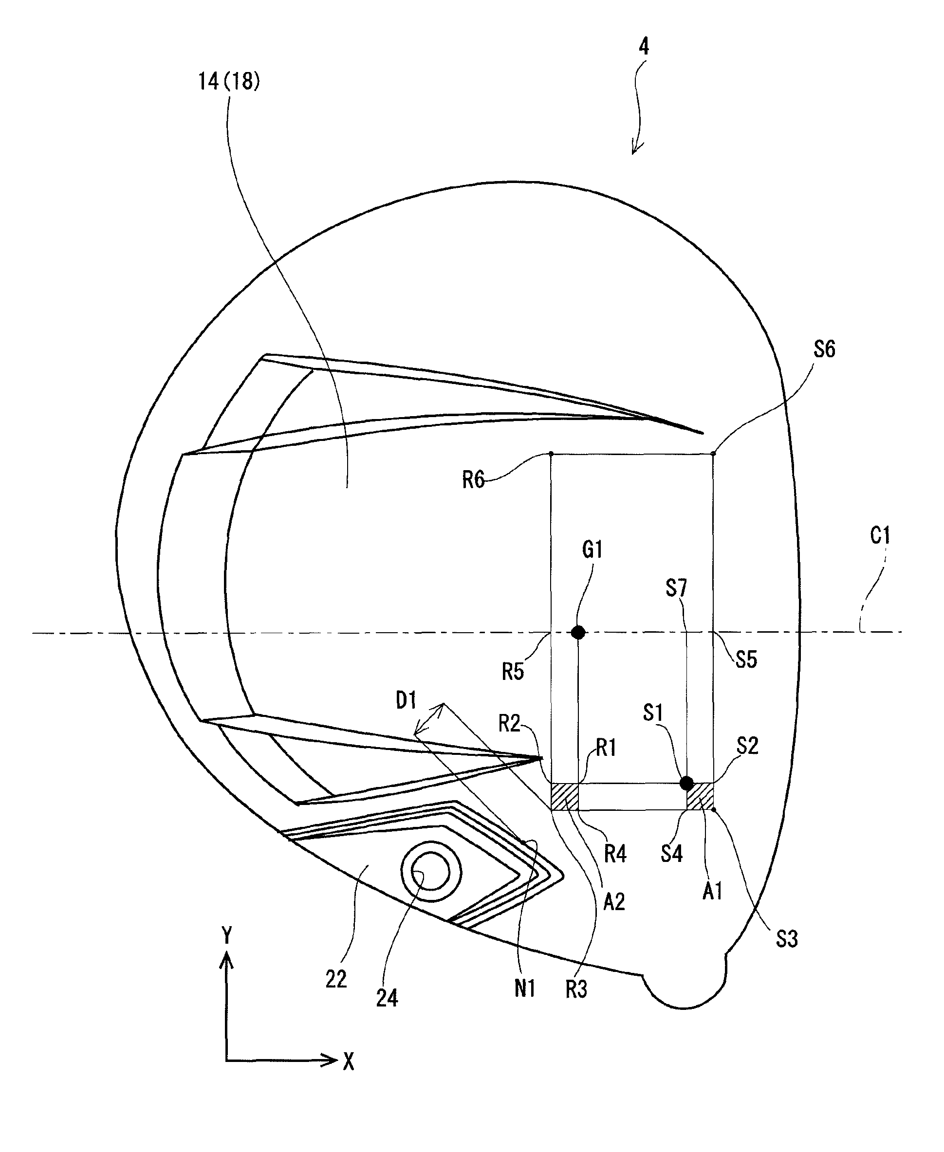
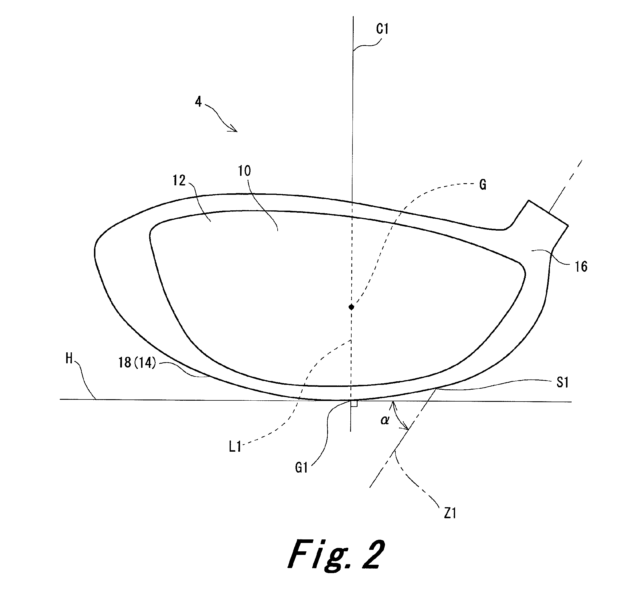
An intersection point between a shaft axis Z1 and a sole surface 18 is defined as S1. A point S2, a point S3, and a point S4 are set on the sole surface 18. An intersection point between a straight line passing through a center of gravity of the head and being perpendicular to the horizontal plane and the sole surface 18 is defined as G1. A point R1, a point R2, a point R3, and a point R4 are set on the sole surface 18. A section A1 and a section A2 are set based on the points. An angle between the shaft axis Z1 and a ground plane is defined as θ. The angle θ exists so that at least a point belonging to the section A1 and at least a point belonging to the section A2 are brought into contact with the ground plane.

Description

[0001]The present application claims priority on Patent Application No. 2011-96882 filed in JAPAN on Apr. 25, 2011, the entire contents of which are hereby incorporated by reference.BACKGROUND OF THE INVENTION[0002]1. Field of the Invention[0003]The present invention relates to a golf club head and a golf club.[0004]2. Description of the Related Art[0005]Various shapes of a sole have been proposed in a golf club head.[0006]Japanese Patent Application Laid-Open No. 2004-8303 discloses a head with a spherical sole having a convex curved surface in a toe-heel direction and a face-back direction. When the head is set at an address lie angle of 45 degrees to 55 degrees, the spherical sole is partially formed in a plane or a recessed surface brought into contact with a standard surface.SUMMARY OF THE INVENTION[0007]In recent years, a head with a sole having a complicated shape has been known. Examples of a cause of the complication include diversification of head functions. For example, w...

Claims


Application Information

Patent Timeline
Patent Type & Authority Patents(United States)
IPC IPC(8): A63B53/06A63B53/04A63B102/32
CPCA63B53/0466A63B2053/0433A63B2053/0491A63B53/06A63B53/047A63B2053/0408A63B53/0408A63B53/0433A63B60/00
Inventor MATSUNAGA, KIYOFUMI
Owner SUMITOMO RUBBER IND LTD
Why Eureka
Eureka Blog
Learn More