
Receiver for interleave division multiplexing cooperative diversity and power allocation algorithm thereof

a cooperative diversity and relay terminal technology, applied in the field of cooperative diversity schemes, can solve the problems of signal transmission overhead, inability to implement the mimo system in uplink, and increase the complexity of relay terminals, so as to reduce complexity and maintain frequency efficiency.

Active Publication Date: 2014-10-28
LG ELECTRONICS INC +1
View PDF8 Cites 3 Cited by
  • Summary
  • Abstract
  • Description
  • Claims
  • Application Information

AI Technical Summary

Benefits of technology

IDMA enables terminals to freely operate as relay terminals with low complexity, maintains high spectral efficiency, and reduces bit error rates by enhancing the signal-to-interference-plus-noise ratio through controlled power allocation.

Problems solved by technology

However, in spite of the advantages of the MIMO system, in general, it is not possible to implement the MIMO system in uplink due to restrictions such as the size, weight, hardware complexity, and the like.
In addition, when the configuration of participating relay terminals, such as the number of relay terminals, changes due to a movement, the channels used by the relay terminals are also inevitably changed, so the relay terminals must be ordered (or aligned) at every transmission, and the like, increasing overhead of signal transmissions.
However, in order to use determined channel codes, relay terminals must need to accurately restore signals and re-encode them, which results in an increase in complexity of the relay terminals.
In addition, when a channel between a transmitter and a relay terminal (a source-relay channel) is unstable, the scheme using an orthogonal code cannot be applicable.
In addition, in order to use determined channel codes, a determined number of relay terminals must participate, which can be hardly achieved in actuality due to a frequency movement of the terminals.
In addition, when there is a change in the configuration of the relay terminals due to a movement of the terminals, overhead of signal transmissions such as a transmission of information regarding ordering of the relay terminals and information regarding a code design, and the like, increases.
Also, when the number of relay terminals that can participate is less than the number of relay terminals required for the determined codes, the scheme using an orthogonal code cannot be applicable.
However, in the DF scheme, the relay terminal decodes the message signal from the transmitter, re-encodes it, and then transmits the same, which is, thus, less affected by noise, but hardware complexity increases due to the decoding of the message signal of the transmitter.
Research reveals that the multi-relay terminal-based cooperative diversity scheme achieves good performance as the number of relay terminals increases, but the length of a time slot allocated for the message signal is reduced to cause a problem in that a bandwidth efficiency is reduced.
The space-time coding relay scheme is effective for a bandwidth utilization and disadvantageous in that hardware complexity increases according to the space-time coding to obtain orthogonality and the space-time coding relay scheme can be applicable only to a particular number of relays.
Research regarding the existing cooperative diversity scheme has been largely conducted on protocols, coding schemes, relay terminal selection schemes, and the like, in case of a single relay terminal, or when the number of relay terminals is uniform or complexity is high and a frequency efficiency is not good in case of multiple relay terminals.
However, in an actual wireless communication network environment, terminals tend to frequently move, and because relay terminals can freely participate in a network or exit from the network, the mentioned related art cooperative diversity scheme can be hardly applicable.

Method used


Image

  • Receiver for interleave division multiplexing cooperative diversity and power allocation algorithm thereof
  • Receiver for interleave division multiplexing cooperative diversity and power allocation algorithm thereof
  • Receiver for interleave division multiplexing cooperative diversity and power allocation algorithm thereof

Examples


Embodiment Construction

[0044]The present invention is applied to cooperative diversity. However, the present invention is not limited thereto and can be applicable to any communication system and method or other copyright-related system and methods to which the technical idea of the present invention can be applied.

[0045]The present invention may be embodied in many different forms and may have various embodiments, of which particular ones will be illustrated in drawings and will be described in detail. However, it should be understood that the following exemplifying description of the invention is not meant to restrict the invention to specific forms of the present invention but rather the present invention is meant to cover all modifications, similarities and alternatives which are included in the spirit and scope of the present invention. The terminology used herein is for the purpose of describing particular embodiments only and is not intended to be limiting of the invention. Unless otherwise defined...


PUM


Abstract

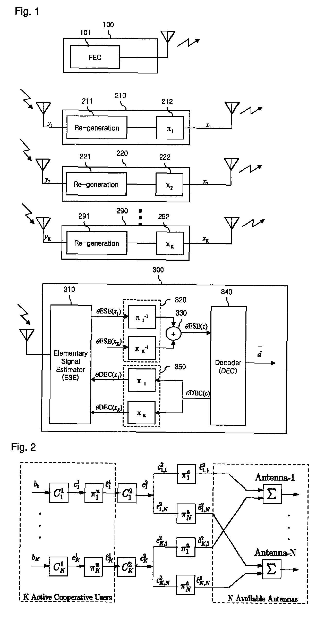
Disclosed is a receiver in a cooperative diversity system including one or a plurality of relays. The receiver includes: a detection unit configured to detect each of signals transmitted from the one or more relays, the one or more signals being generated by the one or more relays and by interleaving a signal from a transmitter; a deinterleaver configured to deinterleave each of the detected signals; a decoder configured to decode and each of the deinterleaved signals thereby to output one or more decoded signals; and an interleaver configured to interleave each of the one or more decoded signals thereby to output one or more interleaved signals, wherein the detection unit receives the one or more interleaved signals and compares them with the respective detected signals to discriminate the original signal transmitted by the transmitter.

Description

TECHNICAL FIELD[0001]The present invention relates to a cooperative diversity scheme.BACKGROUND ART[0002]Research for spatial diversity using a multiple input multiple output (MIMO) system has been actively ongoing in order to overcome performance degradation due to channel fading of radio communication.[0003]The MIMO system, including a transmitter and a receiver each having two or more antennas, provides advantages such as a high data transfer rate, a low error rate, and an increased channel capacity, and the like.[0004]However, in spite of the advantages of the MIMO system, in general, it is not possible to implement the MIMO system in uplink due to restrictions such as the size, weight, hardware complexity, and the like.[0005]As an alternative, a cooperative diversity scheme has been proposed. The purpose of the cooperative diversity scheme is to obtain the advantages of a space diversity gain, a reduction in an error rate, an increase in a channel capacity, and the like, of the...

Claims


Application Information

Patent Timeline
Patent Type & Authority Patents(United States)
IPC IPC(8): H04W52/42
CPCH04W52/42
Inventor LEE, JAE HONGJANG, CHULHEEJO, JUNHO
Owner LG ELECTRONICS INC
Learn More