Protection circuit, battery control device, and battery pack

Inactive Publication Date: 2014-10-28
DEXERIALS CORP
View PDF5 Cites 0 Cited by
  • Summary
  • Abstract
  • Description
  • Claims
  • Application Information

AI Technical Summary

Benefits of technology

[0012]According to the present invention, a terminal is provided at each end of each resistor which is not connected to the low melting metal. These terminals are selected, taking into account a range of voltage variations of the battery unit, for connection to one or more current control element(s) that control the current flowing from the low melting metal to the heating unit. It is thus possible with the present invention to select one or more resistors of the heating unit for heating, taking into account the range of the voltage variations of the battery unit, in order to adjust the quantity of heat used to heat the low melting metal. Viz., according to the present invention, the current control element(s) is connected to the terminal selected taking into account the range of the voltage variations of the battery unit. By so doing, it is possible to positively melt the low melting metal by the heat of the heating unit to interrupt the charging / discharging current path of the battery unit as the broad voltage variations of the battery unit are coped with.

Problems solved by technology

On the other hand, in case the battery unit voltage increases precipitously by some reason or other, the heating element emits excess heat, with the consequence that the heating element is scorched and hence falls into disorder so that the low melting metal may not be disrupted on melting.

Method used


Image

  • Protection circuit, battery control device, and battery pack
  • Protection circuit, battery control device, and battery pack
  • Protection circuit, battery control device, and battery pack

Examples


Embodiment Construction

[0026]A preferred mode for carrying out the present invention will now be described with reference to the drawings. It should be noted that the present invention is not limited to the following mode such that a large variety of modifications may be made without departing from the purport of the invention.

[0027]

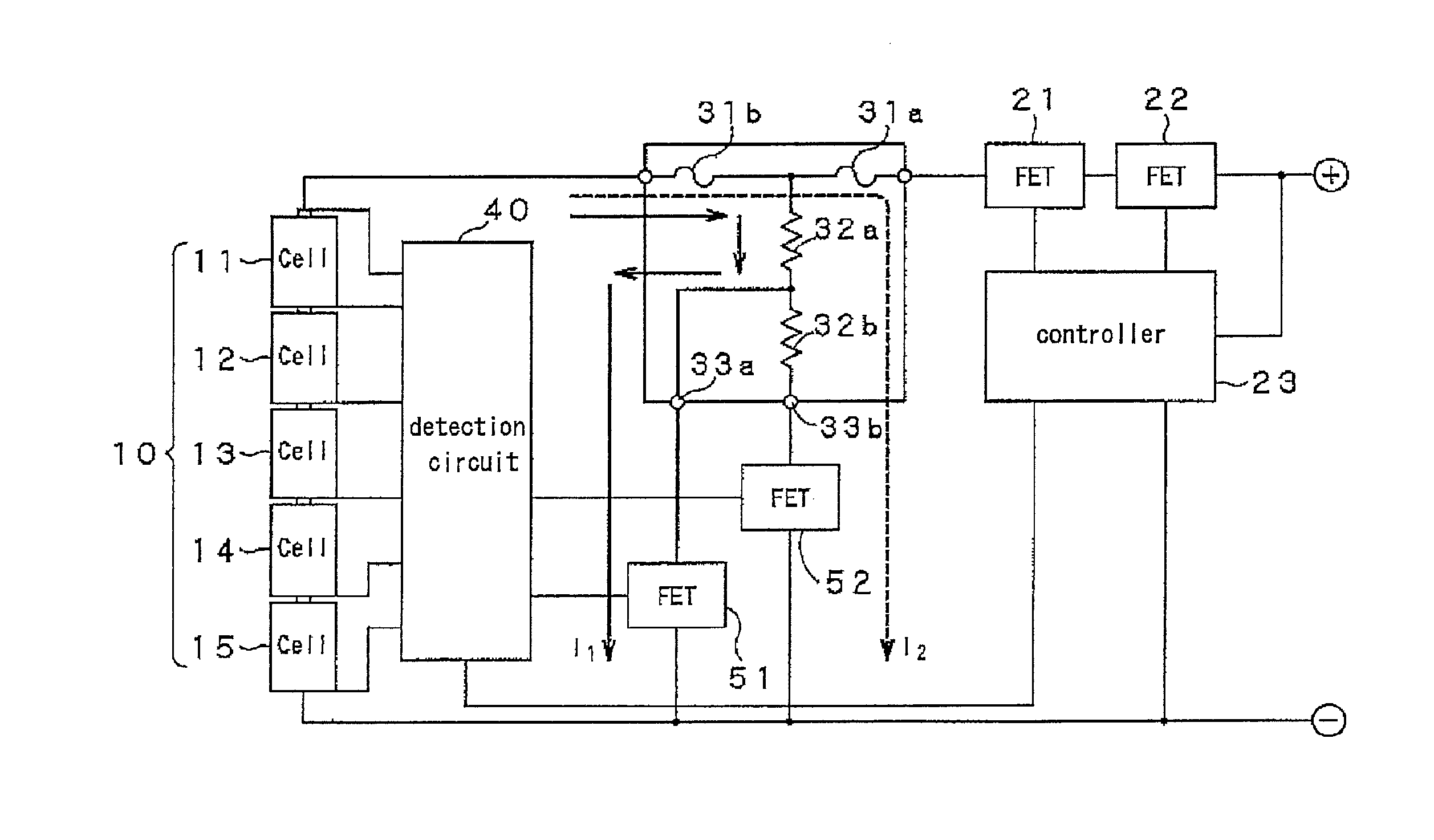
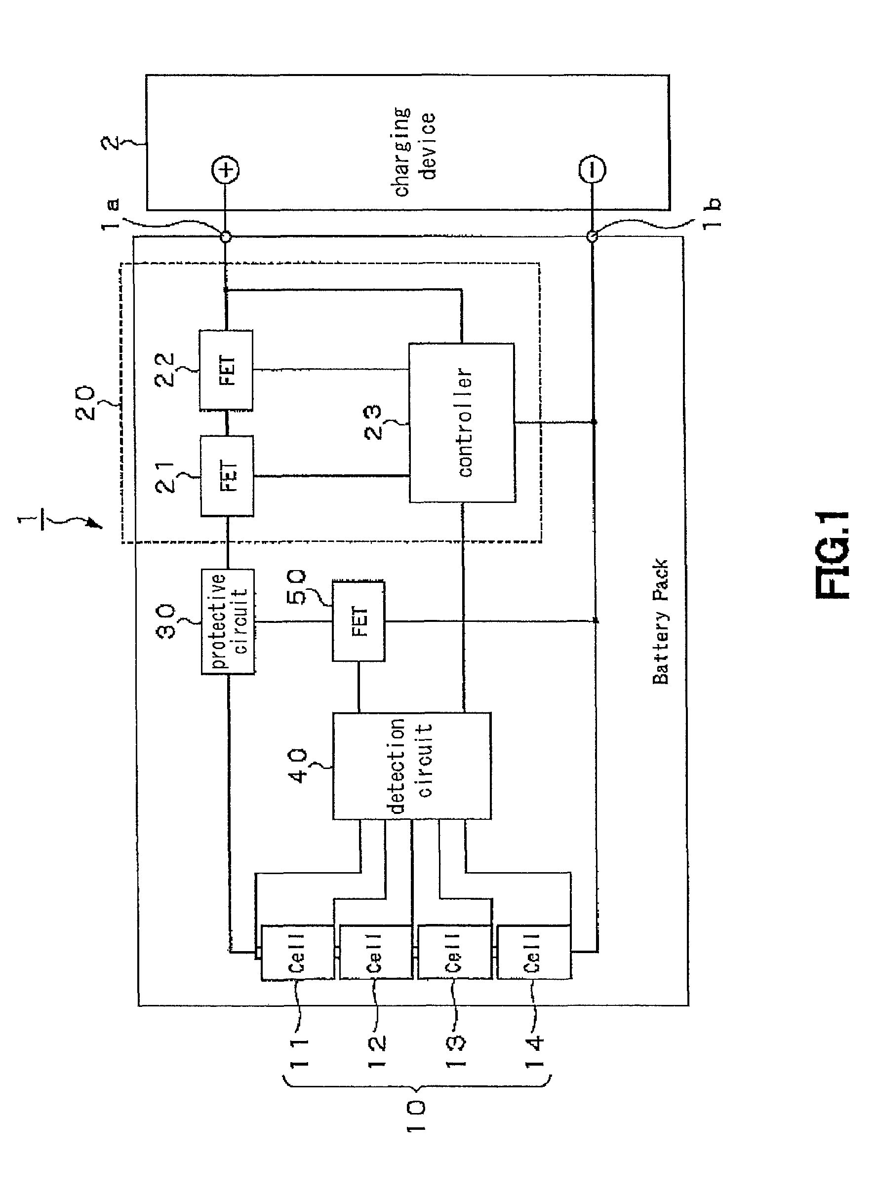
[0028]The protective circuit according to the present invention is a circuit that protects a battery unit composed by a plurality of chargeable / dischargeable battery cells and a charging / discharging control circuit. In use, the protective circuit is built into a battery pack 1 including a battery unit 10 made up of a sum total of four chargeable / dischargeable battery cells 11 to 14 shown for example in FIG. 1.

[0029]Specifically, the battery pack 1 includes the battery unit 10, a charging / discharging control circuit 20, a protective circuit 30, a detection circuit 40 and a current control element 50. The charging / discharging control circuit controls the charging / discharging of ...


PUM

PropertyMeasurementUnit
voltageaaaaaaaaaa
voltageaaaaaaaaaa
voltageaaaaaaaaaa

Abstract

A protective circuit capable of coping with broad voltage variations of a battery unit to interrupt its charging / discharging current path as damages to the heating unit are prevented from occurrence is disclosed. The protective circuit includes fuses, connected to a charging / discharging current path in series between a battery unit and a charging / discharging control circuit, and a heating unit composed by a series connection of resistors. One of two ends of the resistor which is not connected to the peer resistor is connected to a current path of the fuses. The ends of the resistors not connected to the fuses, are provided with a plurality of terminals selected for connection to a current control element that controls the current flowing through the heating unit, as a range of voltage variations of the battery unit is taken into account.

Description

TECHNICAL FIELD[0001]This invention relates to a protective circuit for protecting a battery unit composed by a plurality of chargeable / dischargeable battery cells and a charging / discharging control circuit. This invention also relates to the charging / discharging control device, with the protective circuit built therein, and to a battery pack.[0002]The present application asserts priority rights based on JP Patent Application 2010-034436 filed in Japan on Feb. 19, 2010. The total contents of disclosure of the Patent Application of the senior filing date are to be incorporated by reference into the present Application.BACKGROUND ART[0003]A protective circuit comprised of a heater and low melting metal arranged on a substrate has so far been used as a protective circuit that is able to prevent not only over-current but also over-voltage and that may be used to advantage for secondary batteries for use in e.g., mobile electronic equipment.[0004]In the protective circuit that protects t...

Claims


Application Information

Patent Timeline
Patent Type & Authority Patents(United States)
IPC IPC(8): H01M2/34H02J7/00H01M10/44H02H7/18H01M10/48H01M10/0525
CPCH01M2/348H01M10/0525H02J7/0031H01M10/443H02H7/18H01M10/48Y02E60/12Y02E60/10H01M50/581H02J7/00302H02J7/00306H01M50/20
Inventor MUKAI, KOICHIISHIMARU, MASAHIKOASADA, TAKAHIROKOMORI, CHISATOYONEDA, YOSHIHIROKIMURA, YUUJINAGAKI, SHOKO
Owner DEXERIALS CORP
Why Eureka
Try Eureka