
Rotary steerable push-the-bit drilling apparatus with self-cleaning fluid filter

a push-the-bit and fluid filter technology, which is applied in the direction of directional drilling, drilling pipes, artificial islands, etc., can solve the problems of increasing costs and lost time associated with bit changes, and achieves constant engagement, reduces the risk of component damage, and effectively self-cleaning

Active Publication Date: 2014-10-28
NAT OILWELL VARCO LP
View PDF259 Cites 24 Cited by
  • Summary
  • Abstract
  • Description
  • Claims
  • Application Information

AI Technical Summary

Benefits of technology

The patent text describes a drilling apparatus that can be used to increase the diameter of a borehole during drilling operations. This is achieved by using auxiliary cutting elements on the pistons and piston pads of the apparatus, which can be actuated to open the borehole to a larger diameter. The text also mentions that the fluid flow to the pistons can be increased by aligning a slot in the rotating upper sleeve with a hole in the fixed lower sleeve or by using grooved slots in the fixed lower sleeve. The technical effect of this patent text is to provide drilling apparatus with improved capability to increase the diameter of the borehole, which can be useful in situations where the drill bit becomes worn or occurs a deviation in the path of the borehole.

Problems solved by technology

This results in increased costs and lost time associated with bit changes.

Method used


Image

  • Rotary steerable push-the-bit drilling apparatus with self-cleaning fluid filter
  • Rotary steerable push-the-bit drilling apparatus with self-cleaning fluid filter
  • Rotary steerable push-the-bit drilling apparatus with self-cleaning fluid filter

Examples


Embodiment Construction

[0096]The following discussion is directed to various exemplary embodiments. However, one skilled in the art will understand that the examples disclosed herein have broad application, and that the discussion of any embodiment is meant only to be exemplary of that embodiment, and not intended to suggest that the scope of the disclosure, including the claims, is limited to that embodiment.

[0097]Certain terms are used throughout the following description and claims to refer to particular features or components. As one skilled in the art will appreciate, different persons may refer to the same feature or component by different names. This document does not intend to distinguish between components or features that differ in name but not function. The drawing figures are not necessarily to scale. Certain features and components herein may be shown exaggerated in scale or in somewhat schematic form and some details of conventional elements may not be shown in interest of clarity and concis...


PUM


Abstract

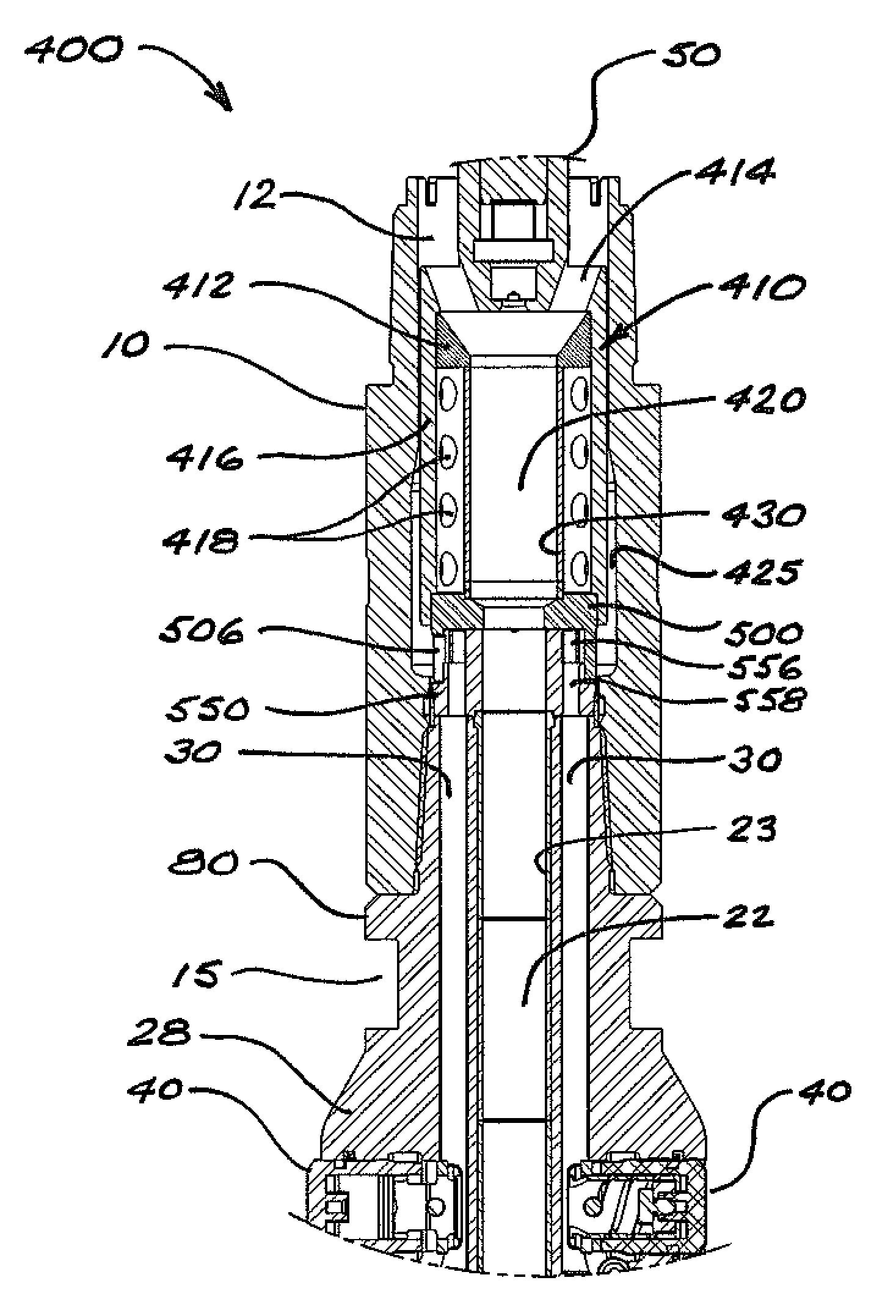
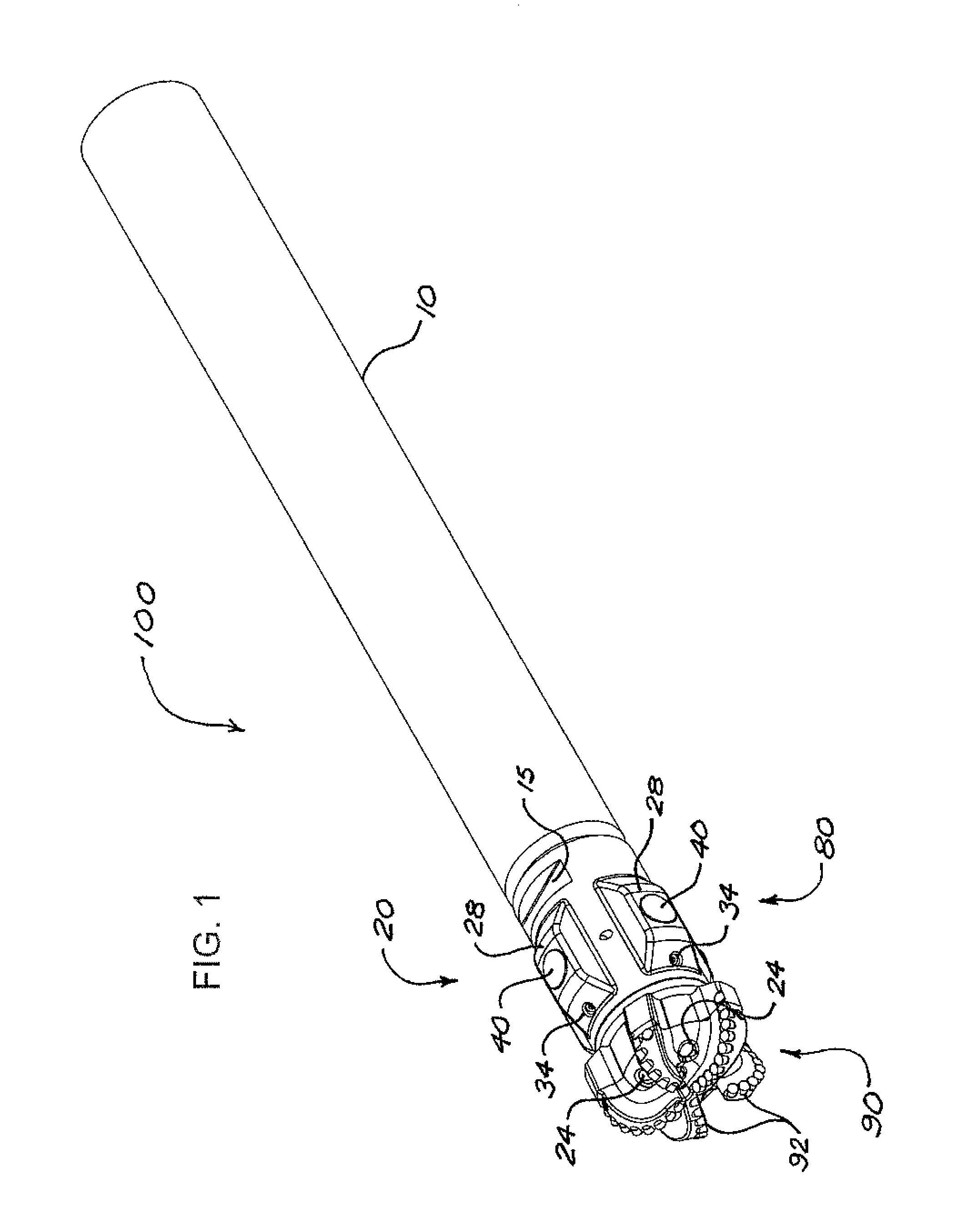
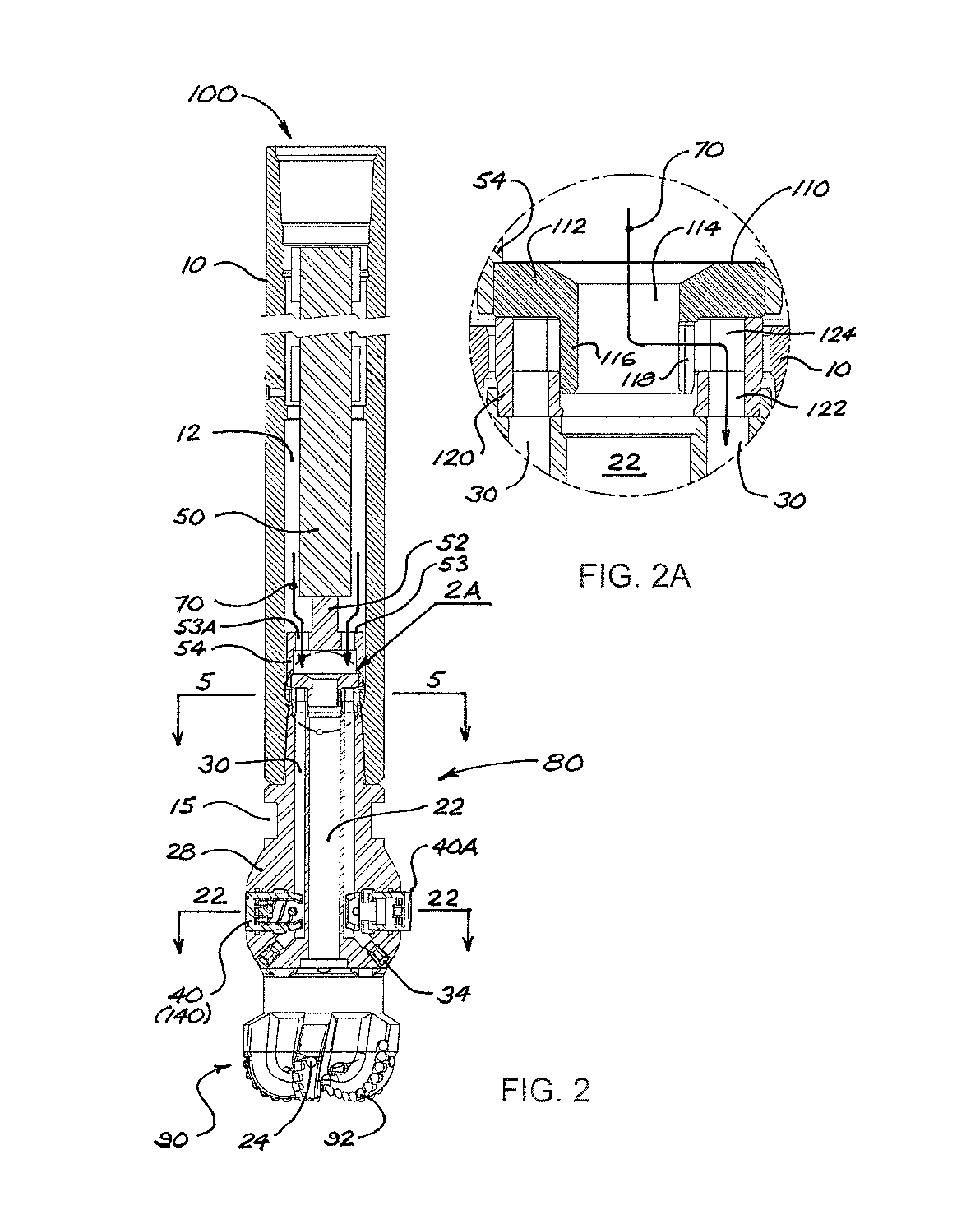
A steerable drilling apparatus includes a control system inside a cylindrical housing connected to a drill bit having radially-extendable pistons. A fluid-metering assembly directs a piston-actuating fluid into fluid channels leading to respective pistons. The control system controls the fluid-metering assembly to allow fluid flow to selected pistons, causing the actuated pistons to temporarily extend in the opposite direction to a desired wellbore deviation, thereby deflecting the drill bit away from the borehole centerline. An upper member in the fluid-metering assembly can be moved to stabilize, steer, and change TFA within the drill bit. The control system and drill bit are connected so as to facilitate removal to change the drill bit's steering section and cutting structure configuration or gauge simultaneously. The apparatus may incorporate a fluid filter module mounted to the control system. The pistons may incorporate auxiliary cutting elements to provide near-bit reaming capability.

Description

CROSS-REFERENCE TO RELATED APPLICATIONS[0001]This application is a continuation in part of U.S. application Ser. No. 13 / 229,643, filed Sep. 9, 2011, and entitled “Downhole Rotary Drilling Apparatus with Formation-Interfacing Members and Control System,” which claims the benefit of U.S. provisional application Ser. No. 61 / 381,243 filed Sep. 9, 2010 and U.S. provisional application Ser. No. 61 / 410,099 filed Nov. 4, 2010, each of which is hereby incorporated herein by reference in its entirety.STATEMENT REGARDING FEDERALLY SPONSORED RESEARCH OR DEVELOPMENT[0002]Not applicable.BACKGROUND[0003]1. Field of the Disclosure[0004]The present disclosure relates generally to systems and apparatus for directional drilling of wellbores, particularly for oil and gas wells.[0005]2. Background of the Technology[0006]Rotary steerable systems (RSS) currently used in drilling oil and gas wells into subsurface formations commonly use tools that operate above the drill bit as completely independent tools...

Claims


Application Information

Patent Timeline
Patent Type & Authority Patents(United States)
IPC IPC(8): E21B17/10E21B7/04E21B7/06
CPCE21B17/1014E21B7/06E21B10/322
Inventor CLAUSEN, JEFFERY RONALDPRILL, JONATHAN RYAN
Owner NAT OILWELL VARCO LP
Learn More