
Ultra-broadband planar millimeter-wave mixer with multi-octave IF bandwidth

a multi-octave, multi-band technology, applied in the direction of electrically long antennas, antennas, electrical equipment, etc., can solve the problem of inability to decouple the if signal from the mixer core the operational rf frequency range of the waveguide is limited to a frequency octave, and the inability to decouple the if signal in a broadband manner. achieve the effect of eliminating band-limiting planar transition

Active Publication Date: 2014-10-21
NATIONAL INSTRUMENTS
View PDF9 Cites 4 Cited by
  • Summary
  • Abstract
  • Description
  • Claims
  • Application Information

AI Technical Summary

Benefits of technology

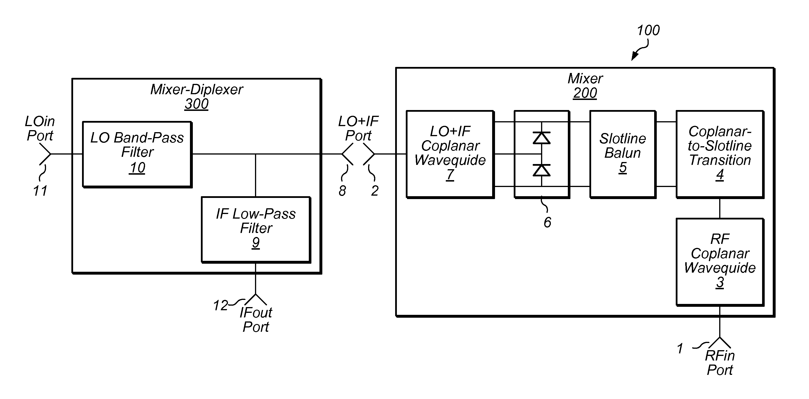
[0007]In view of limitations and problems in the art of broadband microwave mixer design herein is provided, in some embodiments, a microwave mixer structure capable of covering more than a frequency octave of instantaneous bandwidth at microwave frequencies well above 50 GHz at the same time as accomplishing the continuous baseband IF bandwidth over more than six frequency octaves with low conversion loss, unsurpassed conversion loss flatness over the entire IF band, and excellent unit to unit consistency in mixer performance. In some embodiments, one advantage of the broadband microwave mixer described herein may include elimination of band-limiting planar transitions between a LO+IF mixer port and a frequency multiplexer. The frequency multiplexer may provide a frequency separation between LO and IF signals by means of low-pass—band-pass diplexer structure and replacing it with a stand alone diplexer with extremely broadband coaxial interface between the mixer and mixer-diplexer. Another advantage of the broadband microwave mixer may include that the mixer conversion efficiency over a very broadband frequency range is greatly enhanced by optimizing the distance between the mixer diode core and the back-short circuit for the RF signal at LO+IF coplanar waveguide formed by conductive air bridge connecting the coplanar ground strips as well as the distance between the diode mixer core and back-short circuit across the slotline open.

Problems solved by technology

There are however the inherent limitations to the operational bandwidth for IF signal due to the fact that they require a separate transmission media for the IF signal in the form of a low order low-pass filter connected to a balanced side of either RF or LO balun.
With the operational frequencies expanding into microwave and millimeter wave frequencies it becomes more and more difficult to de-couple the IF signal from the mixer core of a double-balanced mixer in a broadband manner due to the shrinking length of balun-transformers and due to the requirement to produce a separate broadband transmission media for the baseband signal.
The main limitation for this class of mixer devices is that the operational RF frequency range of the waveguide is limited to a frequency octave.
Another disadvantage of waveguide mixers is that they require a very precise machining of waveguide cavities which significantly increases the cost for this class of mixers.
The main disadvantages of triple-balanced mixer architectures include the requirement for more LO power to pump eight mixer diodes.
Most of the triple-balanced mixer architectures structures are not planar which leads to much greater difficulty in assembling these mixers at high-end microwave and millimeter wave frequencies.
Current microwave mixer designs, including even so-called planar mixer designs with the Schottky diodes fabricated on the same side of a support dielectric substrate as balun-transformers, exhibit significant limitations of operational bandwidth due to band-limiting planar transitions at any of the mixer ports (particularly for broadband frequency converter applications at frequencies above 50 GHz).

Method used


Image

  • Ultra-broadband planar millimeter-wave mixer with multi-octave IF bandwidth
  • Ultra-broadband planar millimeter-wave mixer with multi-octave IF bandwidth
  • Ultra-broadband planar millimeter-wave mixer with multi-octave IF bandwidth

Examples


Embodiment Construction

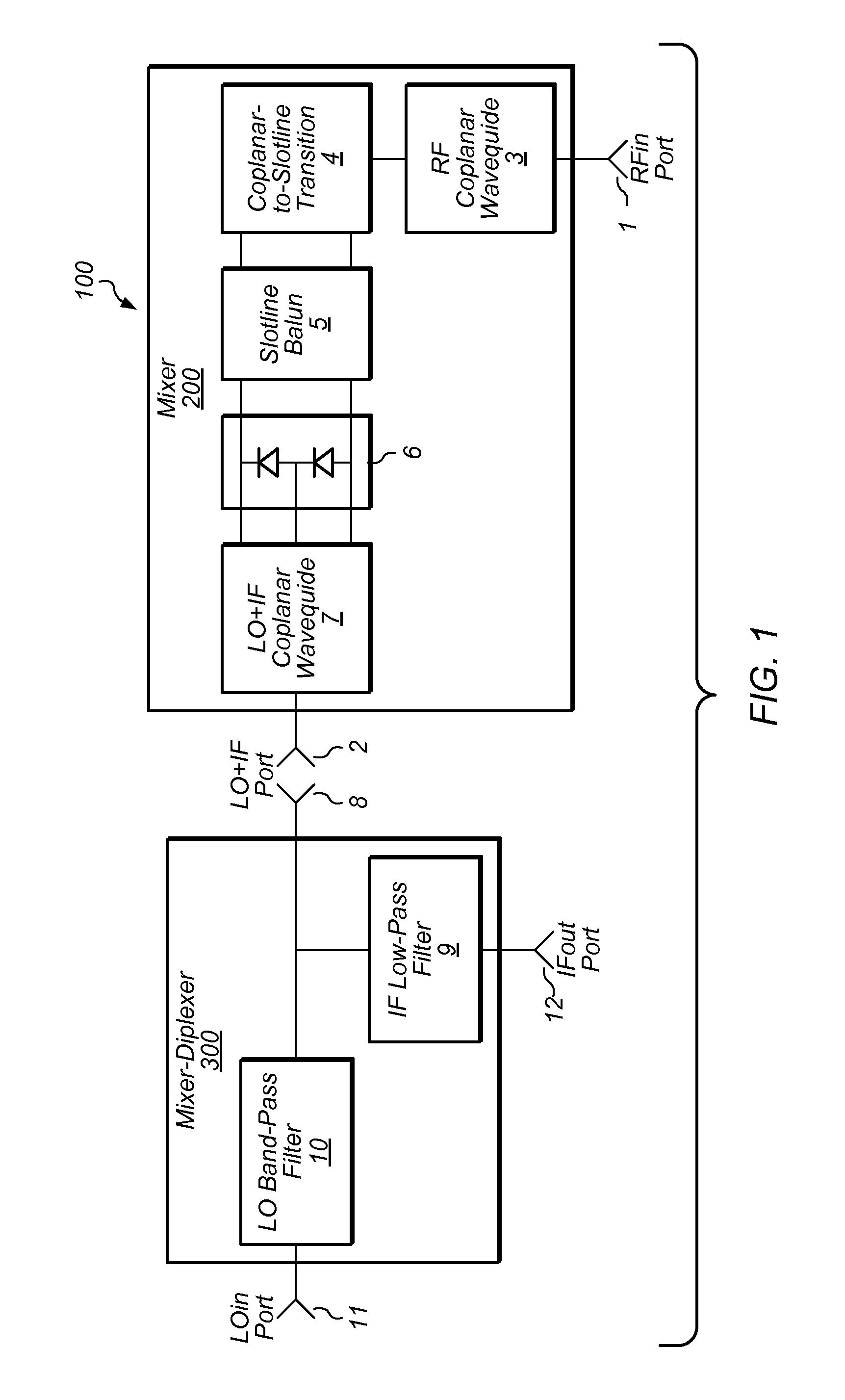
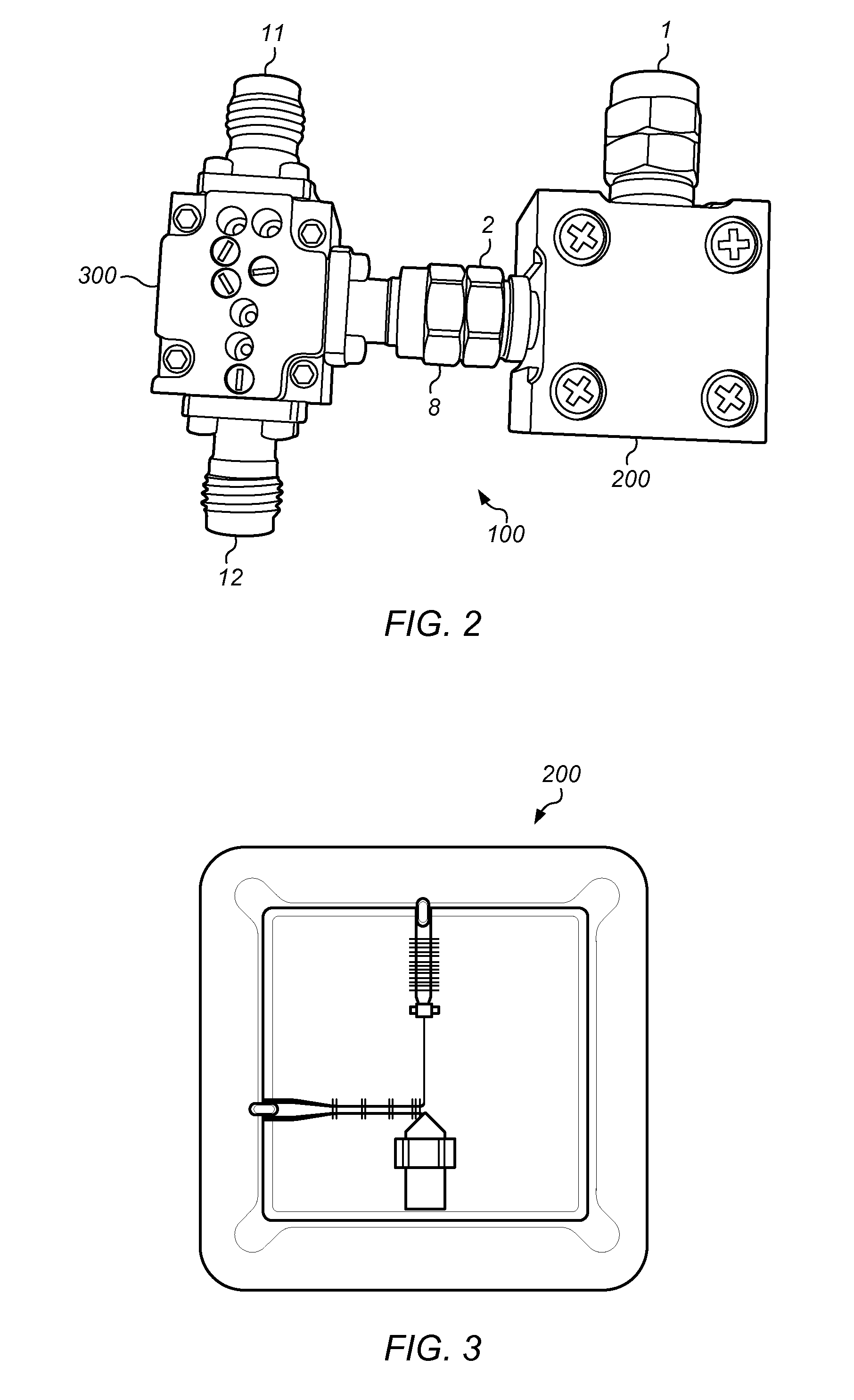
[0025]FIG. 1 depicts a block diagram depicting an embodiment of a system 100 including a planar mixer 200 with stand-alone mixer-diplexer 300. The mixer module may include a first port 1 and a second port 2. The first port may include a coaxial RF port. The second port may include a coaxial LO+IF port. The first port 1 may couple to RF coplanar waveguide 3 which may convey an RF signal to broadband coplanar-to-slotline transition 4 (e.g., of an open / short type). The RF signal may be conveyed in such a manner that one side 32 of coplanar waveguide 3 is terminated in slotline open 34 reflecting the RF signal. The RF signal may be conveyed such that the other side 33 of coplanar waveguide 3 is transformed into a slotline balun 5 with the signal conductor 14 of coplanar waveguide 3 feeding one of the metal strips 15 of slotline balun and the ground plane metal strips 16-17 of coplanar waveguide feeding the opposite polarity metal strip 18 of slotline balun 5.

[0026]The output of slotline...


PUM


Abstract

In some embodiments, a system may include a passive uniplanar single-balanced millimeter-wave mixer. In some embodiments, a three-port diode-tee IC forming a mixer core is coupled between an end of a slotline balun and a second coplanar balun. The operational bandwidth of a mixer structure is enhanced by optimizing the distance between the mixer diode-tee core and the back-short circuits. The frequency separation of LO and IF signals may be accomplished by means of stand-alone three-port filter-diplexer device. The system may allow wider than a frequency octave operational bandwidth for a frequency converter device all the way into millimeter wave frequencies at the same time as supporting the operational bandwidth for baseband IF signal over more than six frequency octaves. In some embodiments, the system may accomplish a 500 MHz to 34.5 GHz continuous IF bandwidth with RF signal sweeping from 33 GHz to 67 GHz and local oscillator at 67.5 GHz fixed frequency.

Description

FIELD OF THE INVENTION[0001]This disclosure relates generally to mixers, and more particularly to implementing a mode conversion single-balanced planar mixer which allows to increase the IF bandwidth for millimeter wave mixer by eliminating the band limiting transitions in the transmission pass for the IF mixer product.DESCRIPTION OF THE RELATED ART[0002]A variety of Radio Frequency (RF) mixers have been developed for the purpose of frequency conversion of a baseband IF signal into RF frequency range by combining (mixing) the IF signal with a local oscillator (LO) signal or for a frequency conversion of the input RF signal into the baseband IF signal by mixing the input RF signal with a LO signal. There are a broad range of applications for mixer devices which include, but are not limited to, communication and data transceivers, a broad variety of radar systems, a broad range of test and measurements instruments like signal generators, spectrum analyzers (SA) and vector signal analy...

Claims


Application Information

Patent Timeline
Patent Type & Authority Patents(United States)
IPC IPC(8): H01P5/10H04B1/18H04B1/04H04B1/26
CPCH01P5/1015H04B1/18H01P1/213H03D7/02
Inventor FELDMAN, ALEXANDER
Owner NATIONAL INSTRUMENTS
Learn More