Image forming apparatus
a technology of forming apparatus and forming tube, which is applied in the direction of electrographic process apparatus, instruments, optics, etc., can solve the problems of aggravating banding and prone to optical writing means
- Summary
- Abstract
- Description
- Claims
- Application Information
AI Technical Summary
Benefits of technology
Problems solved by technology
Method used
Image
Examples
1st embodiment
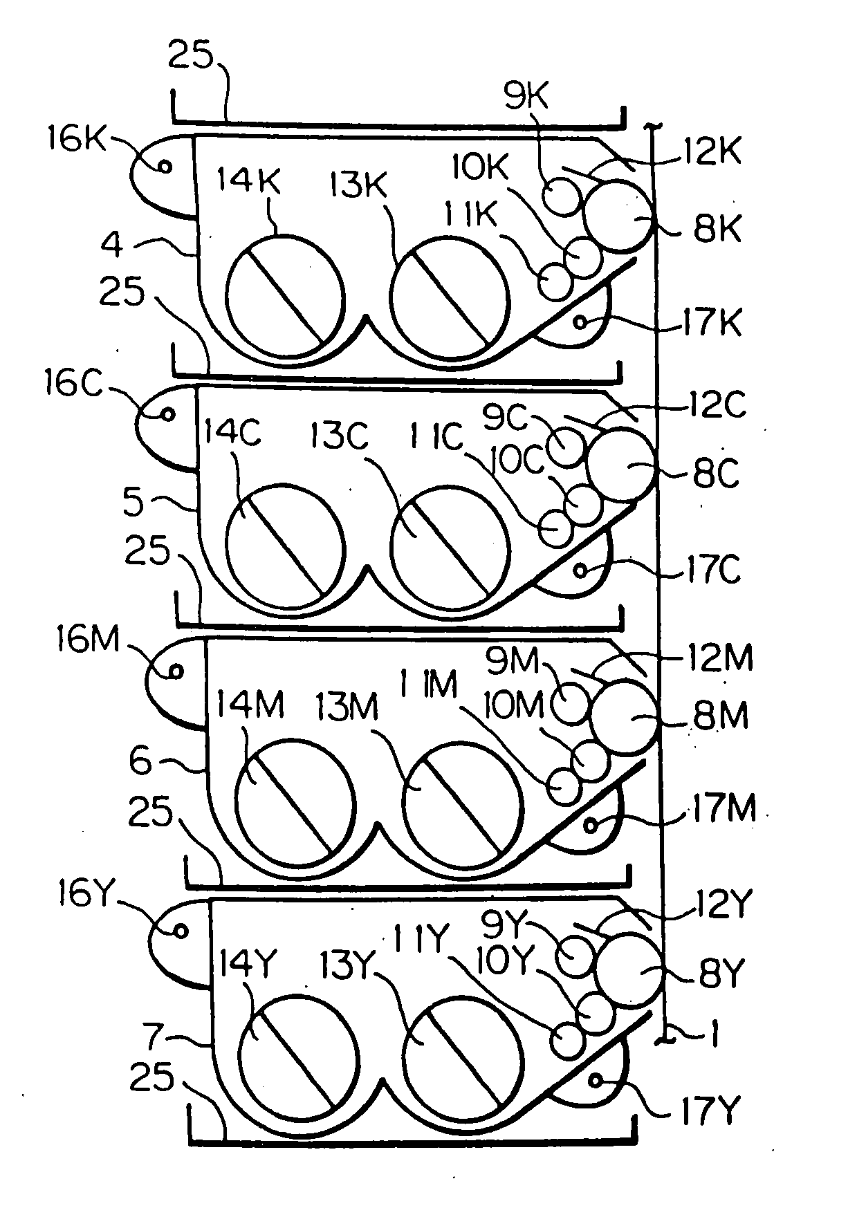
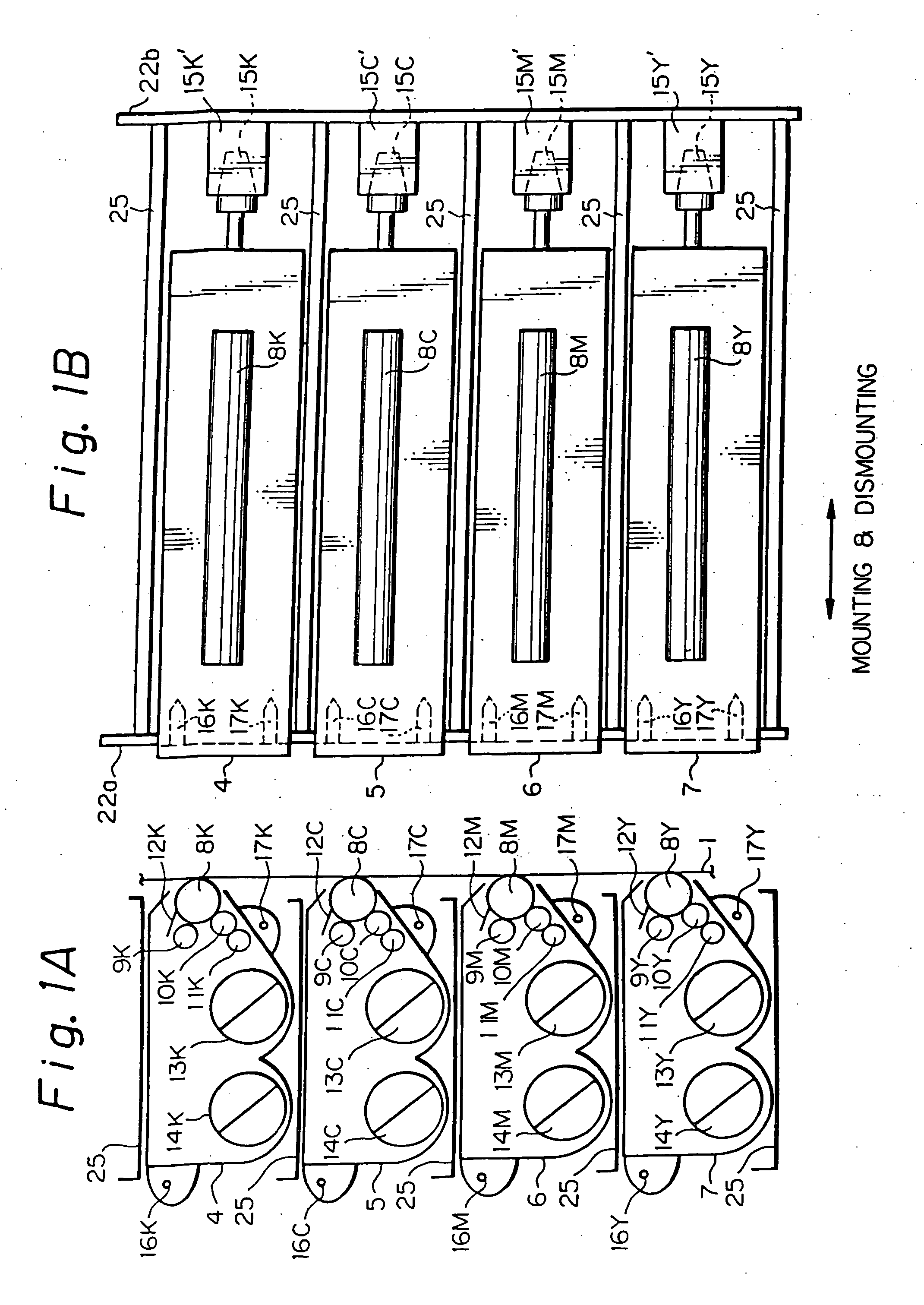
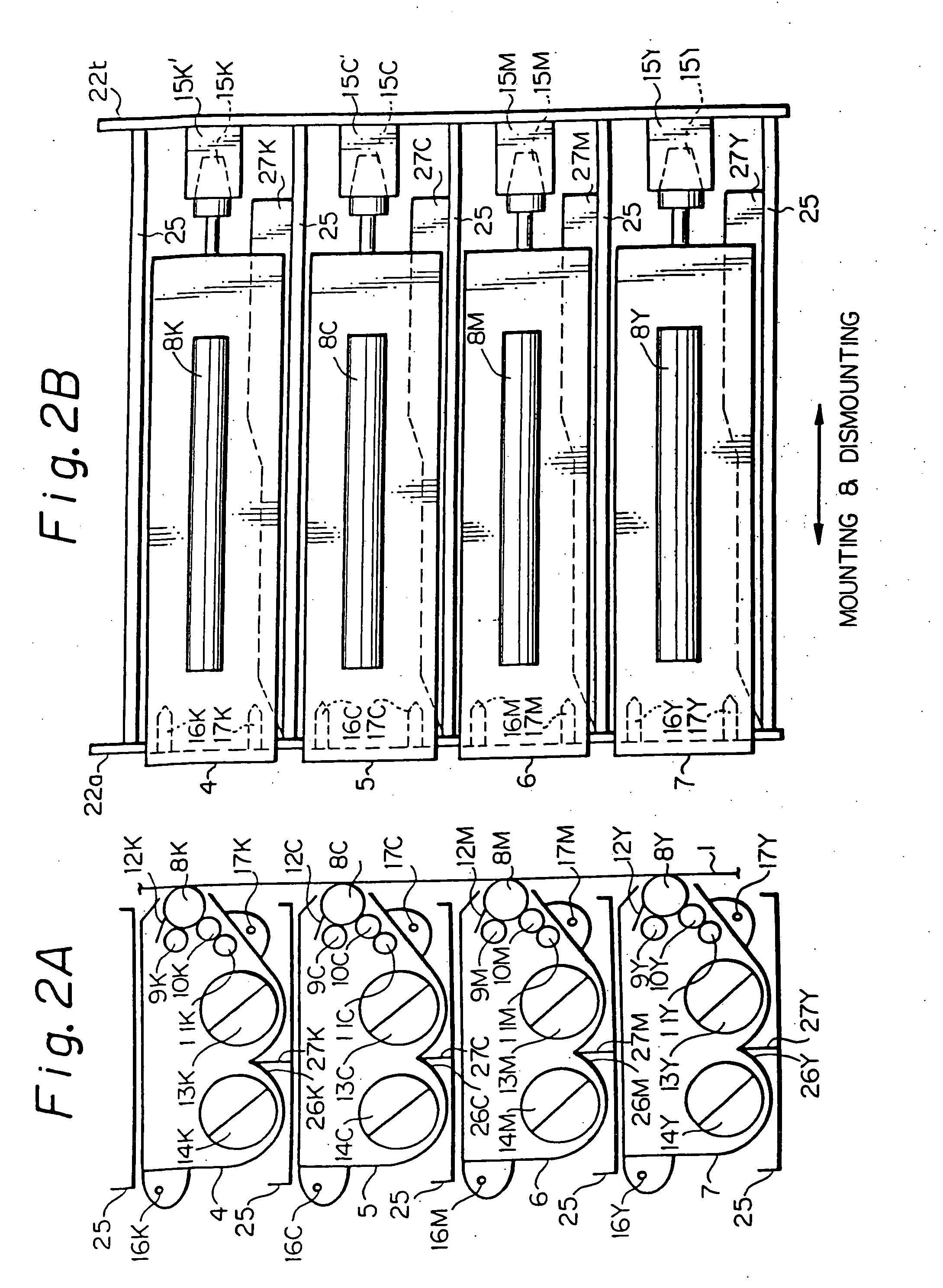
[0109] Basically, this embodiment constitutes an improvement mainly over the conventional image forming cartridge described with reference to FIGS. 44-52. Briefly, the illustrative embodiment is constructed to obviate banding ascribable to the vibration of the photoconductive elements caused by the vibration of the image forming cartridges. Therefore, the embodiment is applicable to both of the construction wherein the photoconductive elements are mounted on the cartridges, more particularly the cases of the cartridges, and the construction wherein when the cartridges supporting the photoconductive elements are mounted to the apparatus body, one or more of the charge rollers, developing means with the developing rollers or the spacing members, and cleaning blades abut against the associated photoconductive elements.
[0110] The following description will concentrate on the construction described with reference to FIGS. 44-49 and 53, i.e., the apparatus of the type including the photo...
2nd embodiment
[0145] This embodiment mainly constitutes an improvement over the construction of the conventional optical writing means described with reference to FIGS. 54 and 55. The structural parts of this embodiment identical with the structural parts of the conventional arrangement are designated by like reference numerals and will not be described specifically in order to avoid redundancy.
EXAMPLE 1
[0146] As shown in FIGS. 9-11, this example is implemented as a full-color image forming apparatus including four image forming cartridges 4-7 stacked one above the other in the direction of gravity. Four optical writing means 104K-104Y are also arranged one above the other in the direction of gravity and associated with the cartridges 4-7, respectively. The writing means 104K-104Y respectively include the adjusting means 330K-330Y stated earlier.
[0147] As shown in FIG. 11, a flat structural member 202 is positioned between nearby ones of the writing means 104K-104Y, i.e., between the base memb...
3rd embodiment
[0169] This embodiment obviates banding by using all or part of the configurations of the examples of the foregoing embodiments.
PUM
 Abstract
Description
Claims
Application Information
 - R&D
- Intellectual Property
- Life Sciences
- Materials
- Tech Scout
- Unparalleled Data Quality
- Higher Quality Content
- 60% Fewer Hallucinations
Browse by: Latest US Patents, China's latest patents, Technical Efficacy Thesaurus, Application Domain, Technology Topic, Popular Technical Reports.
© 2025 PatSnap. All rights reserved.Legal|Privacy policy|Modern Slavery Act Transparency Statement|Sitemap|About US| Contact US: help@patsnap.com


