Refrigerant dryer

a dryer and refrigerant technology, applied in refrigeration devices, heat storage plants, lighting and heating apparatus, etc., can solve the problems of limited control range of speed control, poor energy efficiency, and inability to provide energy-efficient control of cooling capacity, so as to improve the energy efficiency and improve the relationship of energy used

Active Publication Date: 2014-10-14
KAESER KOMPRESSOREN SE
View PDF15 Cites 7 Cited by
  • Summary
  • Abstract
  • Description
  • Claims
  • Application Information

AI Technical Summary

Benefits of technology

The present invention provides a refrigerant dryer and method for cold-drying a gaseous fluid with higher energy efficiency. This is achieved by using an accumulator discharge fluid or refrigerant in the refrigerant dryer and through a method involving cooling the cold accumulator medium using a separate loading heat exchanger, which increases the flexibility in the size and configuration of the accumulator. The method also involves incorporating substances with high thermal conductivity into the cold accumulator medium to improve its effectiveness. The patent also proposes using the flow paths of the discharge loop to further reduce the heat content of the cold accumulator. These improvements result in a more favorable energy efficiency ratio, particularly in part load or zero load situations.

Problems solved by technology

It is, however, problematic to provide an energy-efficient control of the cooling capacity of a refrigerant dryer, since this control has to be effected in adaptation to variable pressure fluid volume flows, pressure fluid moistures and / or pressure fluid temperatures.
While the hot gas bypass control has a relatively poor energy efficiency, it is the limited range of control for the speed control which is problematic in most cases.
An ON / OFF control in an expedient structural implementation is highly efficient but problematical with respect to maintaining a constant temperature of the pressure fluid at the condensate separator inflow.
In order to keep this undesired temperature hysteresis as low as possible, despite limited refrigerant compressor operating cycles, large capacities of the cold accumulator are necessary at simultaneously good heat transfers (i.e., low temperature differences) between the evaporating refrigerant agent, the thermal accumulator mass within the cold accumulator and the pressure fluid flow, which poses structurally contradictory requirements and hence is problematic.
In addition, large temperature differences during heat transfer are basically disadvantageous to the energy efficiency since they are associated with a high “energy production.”
In combination with the likewise required large capacity of the cold accumulator, this poses problems as to the structural space and arrangement of the components and heat exchanger surfaces.
The problem hence includes finding a structural configuration by which large efficient heat exchanger surfaces, short heat conduction paths having a high thermal conduction coefficient, and large or voluminous cold accumulators may be obtained simultaneously with a small structural space and expenditure.
The larger these prior art cold dryers have to be dimensioned, the less favorable the cost structure becomes as a result of the necessarily large and expensive heat exchangers, which moreover require expensive raw materials such as copper and aluminum.

Method used


Image

  • Refrigerant dryer
  • Refrigerant dryer
  • Refrigerant dryer

Examples


first embodiment

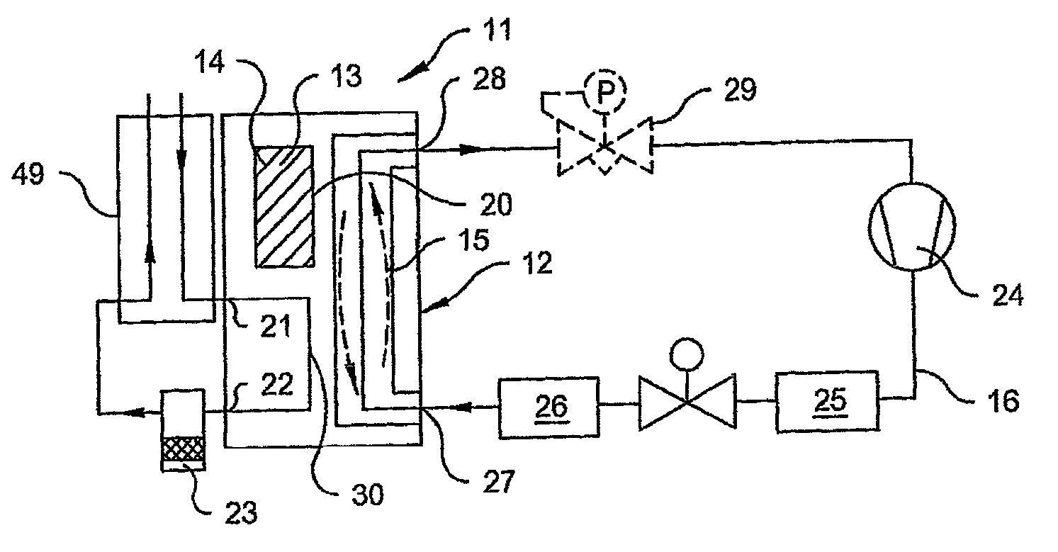
[0062]In FIG. 1, a schematic diagram of an inventive refrigerant dryer 11, in particular for drying compressed air, is illustrated. A central element of the refrigerant dryer 11 is a pressure fluid-refrigerant agent-heat exchanger 30, which first of all comprises a compressed air inlet 21 and a compressed air outlet 22, hence is traversed by a flow of compressed air to be dried, which may also be conveyed in a plurality of compressed air ducts 18 (presently not shown). A condensate separator 23 then follows downstream of the compressed air outlet 22 of the pressure fluid-refrigerant agent-heat exchanger 30 in a manner known per se, which separates the liquid condensed out by the cooling in the pressure fluid-refrigerant agent-heat exchanger 30 from the compressed air flow. The compressed air flow is then made available to further applications that require dry compressed air. Moreover, the present embodiment comprises an air-air-heat exchanger 49 which pre-cools the compressed air fl...

second embodiment

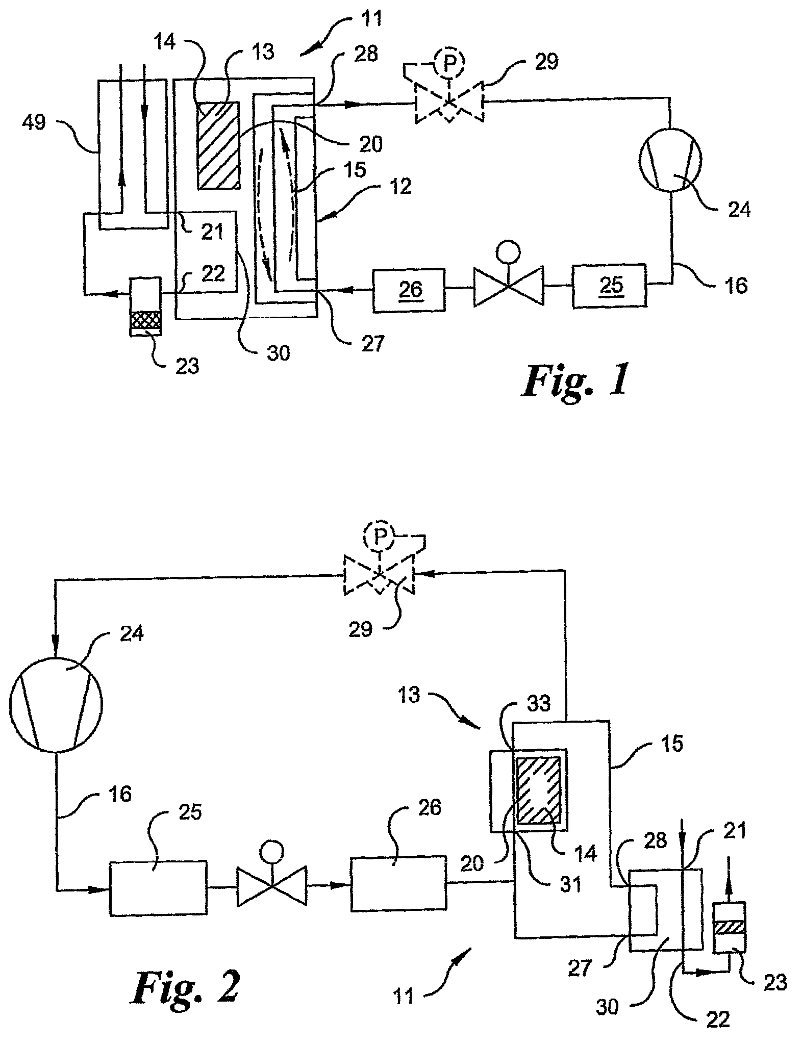
[0075]In FIG. 2, a schematic diagram of the refrigerant dryer according to the invention is illustrated, wherein the accumulator-side heat exchanger 20 and the pressure fluid-refrigerant agent-heat exchanger 30 in this embodiment are realized to be spatially separated and are traversed in parallel during operation of the refrigerant compressor 24 and the primary loop 16, respectively.

[0076]In this arrangement, a lower connection 31 of the accumulator-side heat exchanger 20 is arranged above the pressure fluid-refrigerant agent-heat exchanger 30 and is joined to the lower connection thereof defining the refrigerant inlet 27. Likewise, an upper connection 33 of the accumulator-side heat exchanger 20 is joined to an upper connection 33 of the pressure fluid-refrigerant agent-heat exchanger 30 defining the refrigerant outlet 28.

[0077]During a standstill of the refrigerant compressor 24, refrigerant condenses in the accumulator-side heat exchanger 20 and flows through the lower connectio...


PUM


Abstract

A refrigerant dryer, in particular a compressed air refrigerant dryer, is provided for drying a gaseous fluid while cooling the gaseous fluid using a refrigerant. The dryer includes a pressure fluid-refrigerant agent-heat exchanger (30) in which a cooling of the gaseous fluid takes place directly or indirectly by a refrigerant conveyed in a primary loop (16), one or more refrigerant compressor / compressors (24) for operating the primary loop, and a cold accumulator (13) with an accumulator-side heat exchanger (20) which couples an accumulator discharge fluid to a cold accumulator medium (14). The pressure fluid-refrigerant agent-heat exchanger (30) and the cold accumulator (13) are fluidically connected or can be brought into fluidic connection via a discharge loop (15) for an accumulator discharge fluid. The cold accumulator (13) is arranged, relative to gravity, above the pressure fluid-refrigerant agent-heat exchanger (30), in such a manner that the heated accumulator discharge fluid is conveyed through the discharge loop (15) for cooling in the cold accumulator (13), is cooled there, and subsequently re-conveyed to the pressure fluid-refrigerant agent-heat exchanger (30).

Description

BACKGROUND OF THE INVENTION[0001]The invention relates to a refrigerant dryer, in particular a compressed air refrigerant dryer for drying a gaseous fluid while cooling the gaseous fluid using a refrigerant. The invention also elates to a method for cooling a gaseous fluid in a refrigerant dryer, in particular a compressed air refrigerant dryer.[0002]Refrigerant dryers are known per se. Reference is made to the document European patent application publication EP 1 434 023 A2 as merely one example. By the term cold drying, a method known per se is understood in general as well as according to the present invention, in which the condensable components are removed from a flow of gas by cooling the gas flow below the respective pressure dew point. The term “pressure dew point” is correspondingly understood as the temperature to which the gaseous fluid can be cooled without liquid condensing out. Cold dryers are used in particular for drying compressed air by cooling the compressed air f...

Claims


Application Information

Patent Timeline
Patent Type & Authority Patents(United States)
IPC IPC(8): F25D11/00F25D17/06F25D17/02B01D53/26F28D20/02
CPCB01D53/265F28D20/02F25B2400/24Y02E60/145Y02E60/14
Inventor DERING, KRISTIANFEISTHAUER, MICHAELFREDENHAGEN, ANDREASFOERSTER, ANDREASKOBELT, KLAUS-ULRICH
Owner KAESER KOMPRESSOREN SE
Why Eureka
Try Eureka