
Redundancy in process control system

a process control system and redundancy technology, applied in the direction of electrical programme control, program control, instruments, etc., can solve the problems of limited redundancy, large and complex industrial process, and the connection e.g. between the server and the field or another device connected thereto may be completely lost or otherwise subject to interferen

Inactive Publication Date: 2014-10-07
METSO AUTOMATION OY
View PDF10 Cites 2 Cited by
  • Summary
  • Abstract
  • Description
  • Claims
  • Application Information

AI Technical Summary

Benefits of technology

[0008]An advantage of the arrangement of the invention is that it is always possible to select the best ones from among parallel data units transferred via parallel connections. This enables redundancy to be arranged so as to also takes into account problems in data transfer that impair the quality of the data units transferred. Redundancy based on comparing the property information on parallel data units provides high-speed action as far as the application using the data units is concerned also when some of the connections fails, i.e. a delay caused by activating a new, substitutive connection (e.g. via a secondary server) is avoided.

Problems solved by technology

An industrial process, such as a paper making process or a power station process, is very extensive and complex, including many variables.
The solution disclosed in WO 0 023 857 does not, however, take any other error situations but server or connection failure into account, thus providing limited redundancy.
Even if a server were working correctly, the connection e.g. between the server and a field or another device connected thereto may be completely lost or otherwise subjected to interference.

Method used


Image

  • Redundancy in process control system
  • Redundancy in process control system
  • Redundancy in process control system

Examples


first embodiment

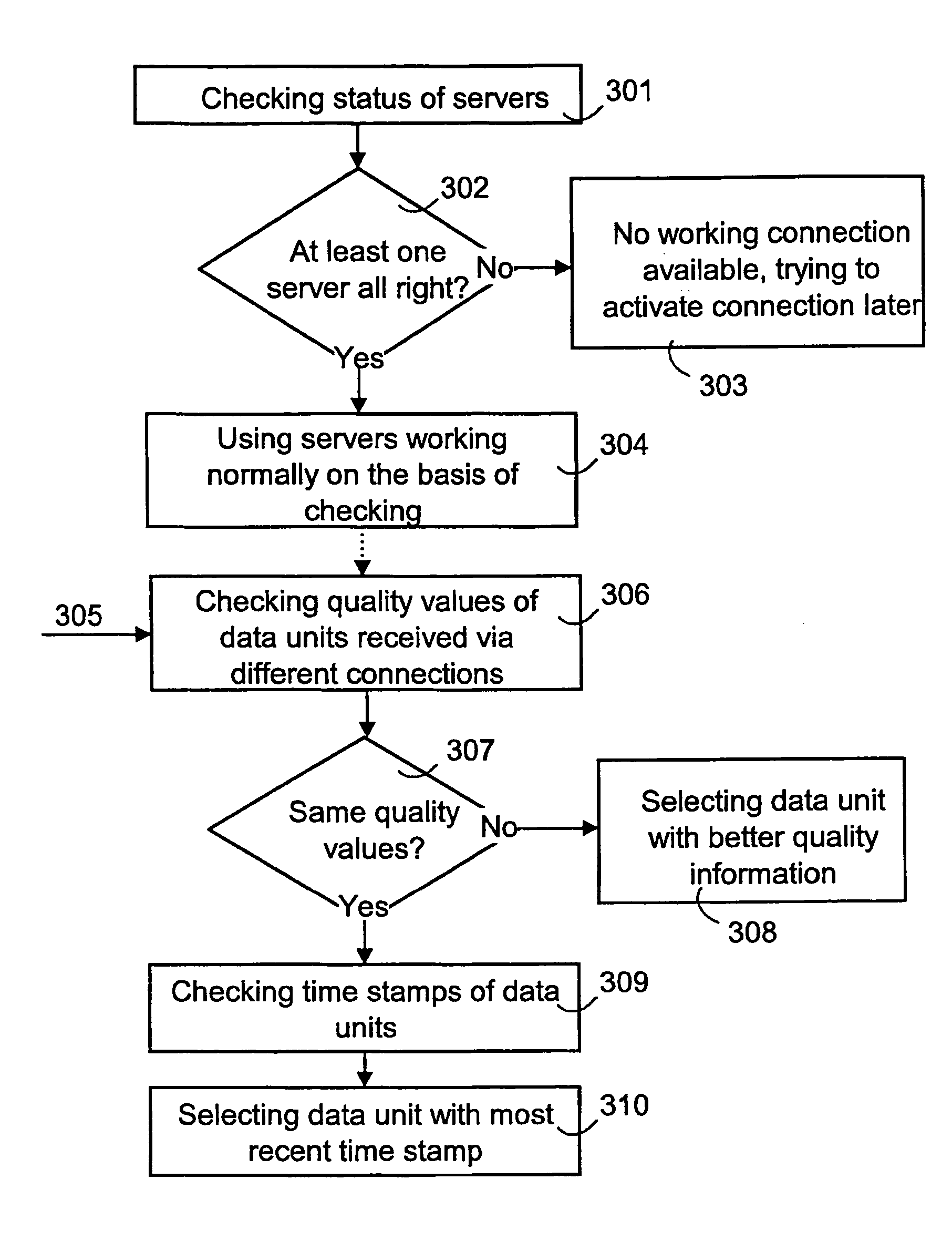
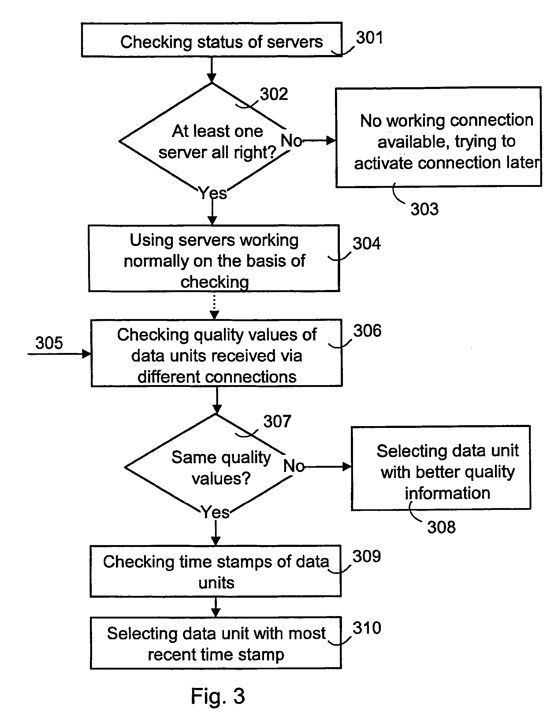
[0036]FIG. 4 illustrates a redundancy configuration wherein redundancy is arranged for an OPC server OPCS (including connections to one or more devices DEV), an OPC client functionality OPCC and an application APP. The servers OPCS provide both OPC clients OPCC with the same data units. Preferably in the manner illustrated in FIG. 3, the OPC clients OPCC select a server and the best ones from among the parallel data units on the basis of the property information on the parallel data units and the predetermined order criteria (on the basis of quality and / or time stamp information) and transmit them to the applications APP. In the embodiment of FIG. 4, preferably one of the applications APP is active, in which case the passive application and the data units provided thereto by the OPCC are used when problems are detected in the operation of the active application. Preferably, the application used in the OPCC is such an application which uses a connection the data units transferred vi...

second embodiment

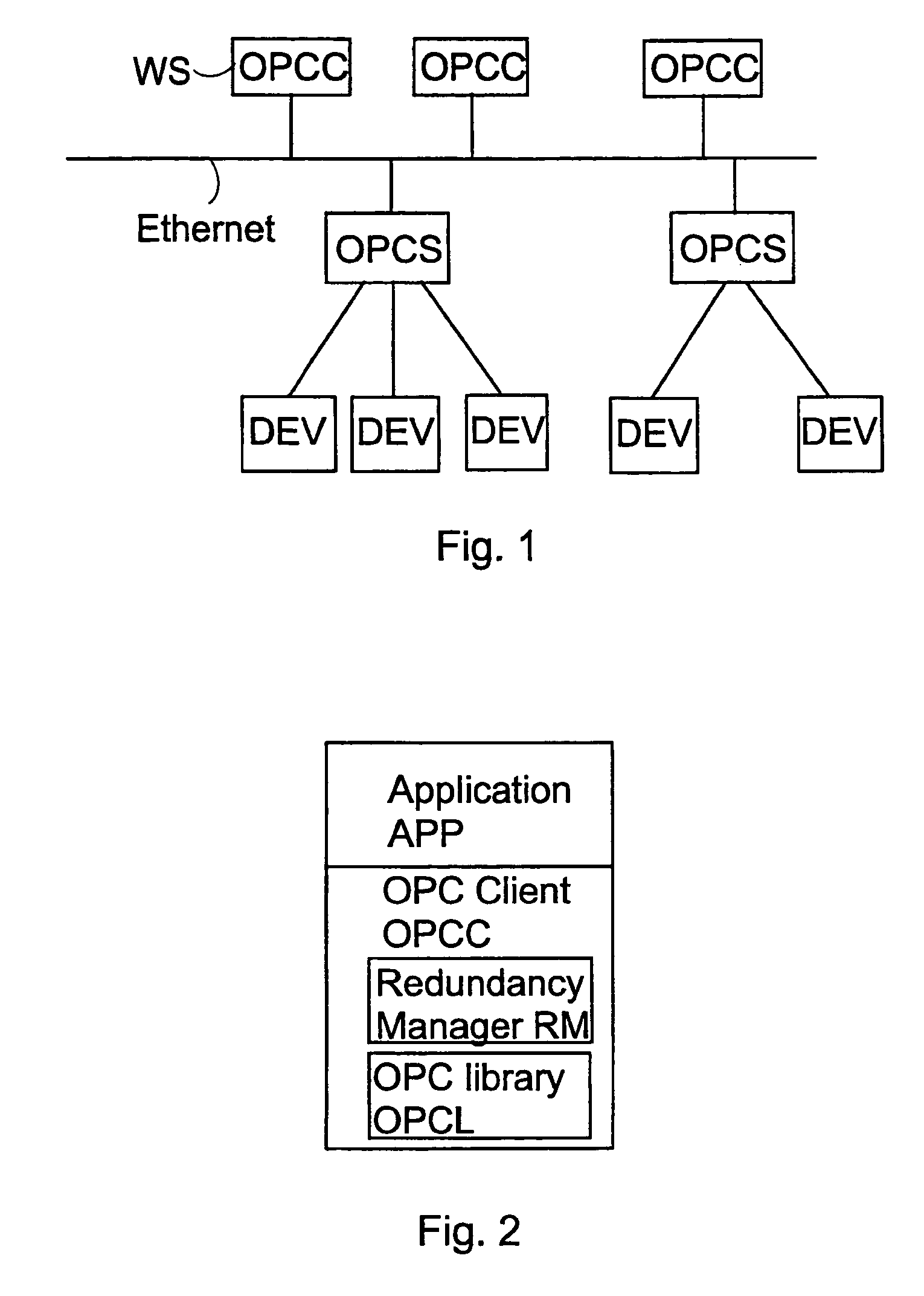
[0037]FIG. 5 illustrates a redundancy configuration wherein an application APP utilizes two OPC client functionalities OPCC. Redundancy is thus arranged for the OPC server OPCS and the OPC client functionality OPCC. The redundancy manager RM may operate as illustrated in FIG. 3, i.e. it may always select data units delivered to the OPCC via a better logical connection for the application APP. The application APP selects, according to its own criteria, a data unit delivered by another OPCC for its use. The APP may select the data unit on the basis of the properties of its payload, e.g. on the basis of the time stamp determined in the payload. In the embodiments disclosed in FIGS. 4 and 5, it must be ensured that only one of the clients OPCC transmits data (write connection) back to the servers OPCS and further to one or more devices DEV.

third embodiment

[0038]FIG. 6 illustrates a redundancy configuration wherein redundancy is arranged for OPC servers OPCS1, OPCS2, thus providing an OPC client OPCC with parallel logical connections. The RM may select a data unit, preferably in the manner illustrated in steps 305 to 310 in FIG. 3. FIG. 6 illustrates a situation wherein the client device OPCC has a need to receive data units from three devices DEV1, DEV2 and DEV3. Three connection pairs are then formed: 1-1, 2-1; 1-2, 2-2 and 1-3, 2-3. In the example of FIG. 6, it is detected, preferably on the basis of the checking illustrated in FIG. 3, that the data units transferred to the device DEV1 via the connection 1-1- used by the OPC server OPCS1 are of poor quality, or that they are missing altogether, in which case the connection 2-1 of the server OPCS2 and the data units transferred therethrough are used in the application APP of the OPC client device OPCC. However, the connection 2-2 provided by the server OPCS2 for the device DEV2 is ...


PUM


Abstract

The invention relates to a method and an apparatus for arranging redundancy in a process control system comprising at least one client device, at least one data source and at least one server device providing data transfer between the client device and the data source. The method comprises arranging, for the client device, at least two parallel logical connections for transferring substantially the same data between at least one data source and the client device. At the client device, property information on data units transferred via different logical connections is checked, the client device being provided with predetermined order criteria for the property information. At the client device, property information on parallel data units transferred via different logical connections is compared. Data units delivered via the logical connection having, according to the predetermined order criteria, the best property information are selected for the use of one or more applications processing the data units.

Description

[0001]This is a Continuation of Application No. PCT / FI03 / 00176 filed Mar. 7, 2003. The entire disclosure of the prior application is hereby incorporated by reference herein in its entirety.BACKGROUND OF THE INVENTION[0002]The invention relates to arranging redundancy in a process control system.[0003]In an industrial process, a highly automatized system is used for ensuring that the process operates in a correct manner. An industrial process, such as a paper making process or a power station process, is very extensive and complex, including many variables. An information system used for controlling an industrial process is responsible for various tasks relating to collecting, distributing, storing and presenting process properties as well as to process control. A process control system typically comprises a large number of work stations that operate independently or controlled by an operator. Such work stations carry out different process control related tasks, such as processing of...

Claims


Application Information

Patent Timeline
Patent Type & Authority Patents(United States)
IPC IPC(8): G06F15/16G05B9/03G05B19/418H04L29/06H04L29/08
CPCG05B9/03H04L67/12H04L69/329G05B19/4185G05B19/4186G05B2219/34263G05B2219/33125G05B2219/31121H04L67/42H04L29/06H04L67/40G05B2219/31208H04L67/02H04L9/40H04L67/01H04L67/133
Inventor LAHTINEN, ESAKARAILA, MIKA
Owner METSO AUTOMATION OY
Learn More